1 Wire One Wire Alternator Wiring Diagram Chevy
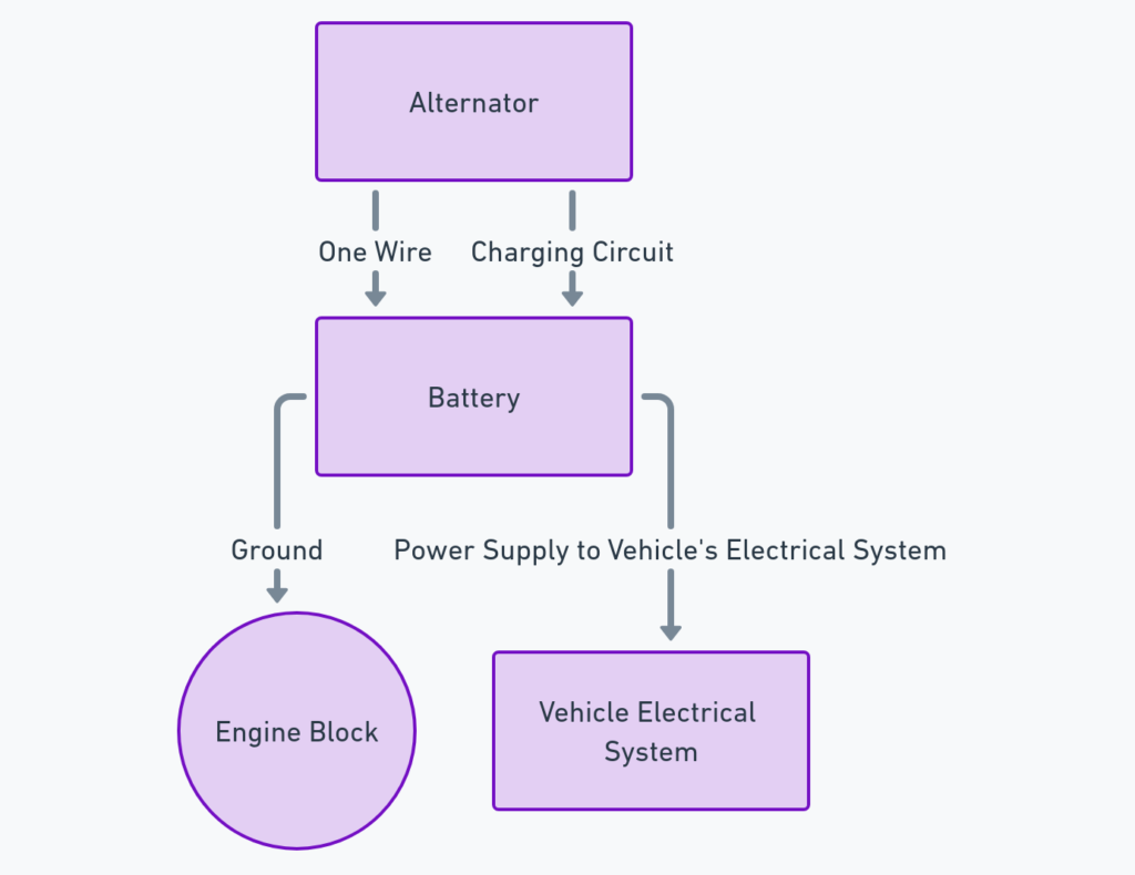
A 1 wire alternator has only one main charging wire which provides battery sensing and charging current. They are designed to be simple and compact. General Motors began using these alternators in the early 1960s all the way up to the mid-1980s on many of their vehicle models.
Some key advantages of 1 wire alternators:
- Compact size and minimal wiring
- Automatically turns on/off based on sensing voltage at alternator output post
- Lower component cost due to simplicity of design
1 Wire One Wire Alternator Wiring Diagrams Chevy
Diagram 1:

Diagram 2:

Diagram 3:

Diagram 4:

Diagram 5:

How Does a 1 Wire Alternator Work?
Inside a typical GM 1 wire alternator there are two internal voltage regulators – a switching regulator and a sensing regulator.
The switching regulator monitors voltage at the alt output terminal. When the key is turned on and the sensing voltage is below a preset level (usually 13.5V), the regulator engages the alternator to start charging.
The sensing regulator monitors voltage coming off the alternator internally and adjusts the field current to maintain a steady system voltage (around 14V). This allows the 1 wire GM alternator to automatically turn on/off based on demand.
1 Wire GM Alternator Wiring Overview
Here is a quick overview of how a GM 1 wire alternator is wired up:
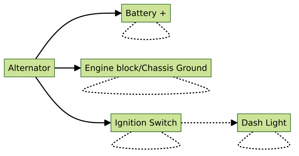
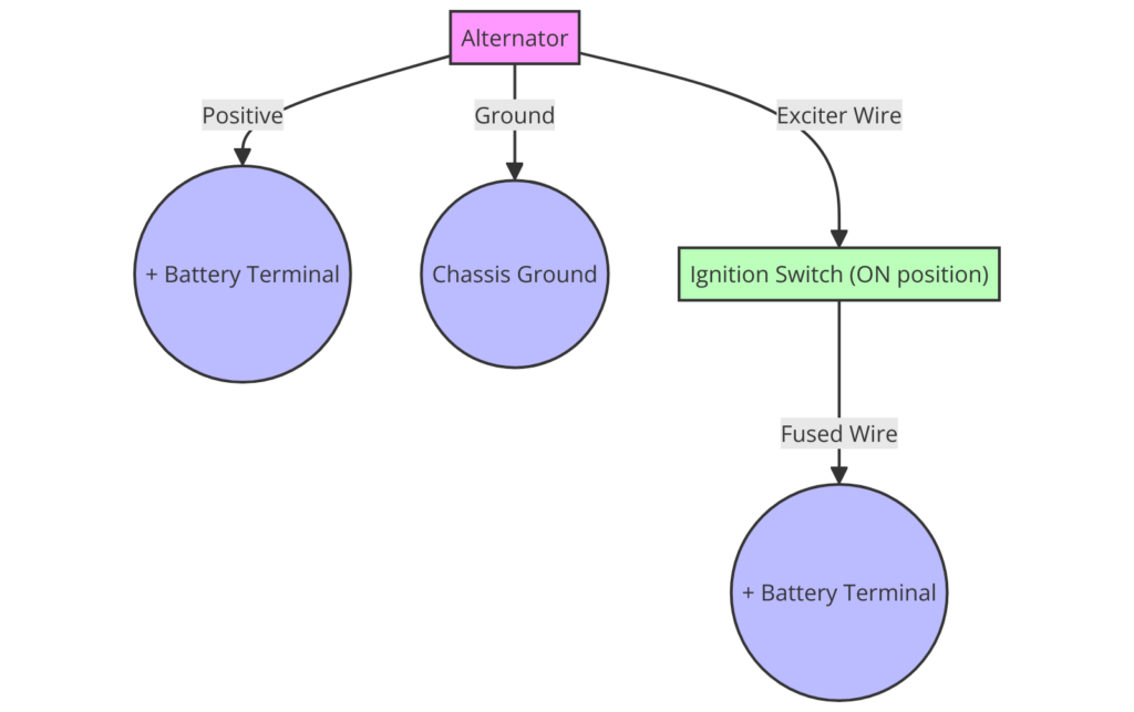
- A single large (typically 8-10 gauge) charge wire runs from alternator “bat” terminal to the battery positive post. This handles all charging current.
- The alternator case itself is grounded directly to the vehicle chassis or engine block for a ground connection.
- Small 12V ignition wire connects to ignition source when key is on to excite alternator field coil at startup. This allows the alternator to start charging when the vehicle is started up.
- Warning lamp wire (optional) can be wired from alternator field terminal to dash light to indicate malfunction.
That’s the basics! Now let’s look at a couple common examples.
Typical GM 1 Wire Alternator Diagram
As you can see this is a very simple setup with a single large charge wire to the battery, the grounded alternator housing, and a small 12V ignition wire to activate the voltage regulator.
An indicator light can also be wired between the “R” terminal and fuse box if desired. This light will come on if there is a charging system problem.
Key things to note in this diagram:
- Large charge wire (often orange 10 gauge) to battery needs to handle full charging amp load. Upgrade wire gauge as needed if longer run is required.
- Solid ground connection with short ground strap avoids many charging issues.
- Small ignition wire can be 18-16 gauge – only needs to provide exciter coil voltage. Common sources are fuse box, ignition switch, or starter solenoid.
Let’s look at one more common 1 wire alternator setup…
1983-1986 Chrysler Alternator Wiring
Chrysler used similar 1 wire internally regulated alternators in many 1983-1986 models.
As you can see, very similar to the GM setup other than tapping power for the ignition wire from the coil positive terminal when key is on. This Chrysler 1 wire alternator diagram shows the basic connections needed in a simple, compact package.
Diagnosing 1 Wire Charging Problems
The simple design of a 1 wire alternator means less wiring confusion when troubleshooting, but there can still be issues. Here are a few quick checks:
- Inspect and re-tighten all wiring connections
- Check for solid ground cable bond between alternator case and battery negative post
- Test ignition wire for 12V key-on power to ensure voltage regulator engagement
- Check brushes and slip rings for excessive wear or carbon tracking (may need alternator rebuild)
If voltage regulator is suspect, test alternator output voltage directly at alt terminal with volt meter to confirm proper charging voltage.
Conclusion
That wraps up this overview on wiring a 1 wire GM alternator. The simple yet effective design still makes these alternators popular today in auto restoration and custom vehicles where a compact charging system is needed.
Let me know in the comments if you have any questions on the wiring diagrams or troubleshooting these classic GM 1 wire alternators!
