1984 F150 Wiring Diagram Decoded: Repair Tips for your Truck
The 1984 Ford F150 brings up images of a hardy, reliable pickup truck designed for hard work and outdoor adventure. Over 30 years later, many of these iconic trucks are still on the road. However, ensuring proper electrical operations is key to getting the most miles out of your classic F150.
So what’s the secret for hassle-free electrical repairs and maintenance? Understanding the 1984 Ford F150 wiring diagram.
The wiring diagram provides a road map to trace each wire and connector for lights, accessories, engine controls, and more. With a basic working knowledge of the diagram, you’ll be able to quickly diagnose issues, replace worn parts, and keep your 1984 F150 running like new.
In this guide, we’ll cover everything you need to know about the 1984 Ford F150 wiring diagram including:
- Key components like the ignition switch and alternator
- Dash accessories, lights, and bed power
- How to navigate the wiring schematic
- Best practices for safe, effective repairs
Follow along as we unlock the secrets of the 1984 Ford F150 wiring system!
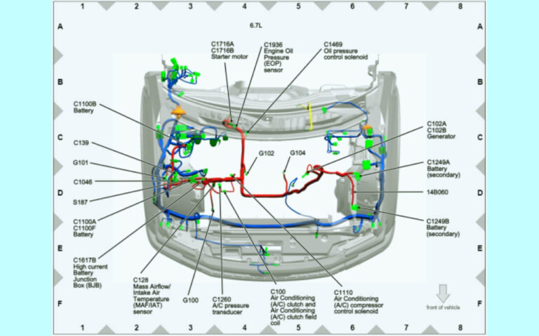
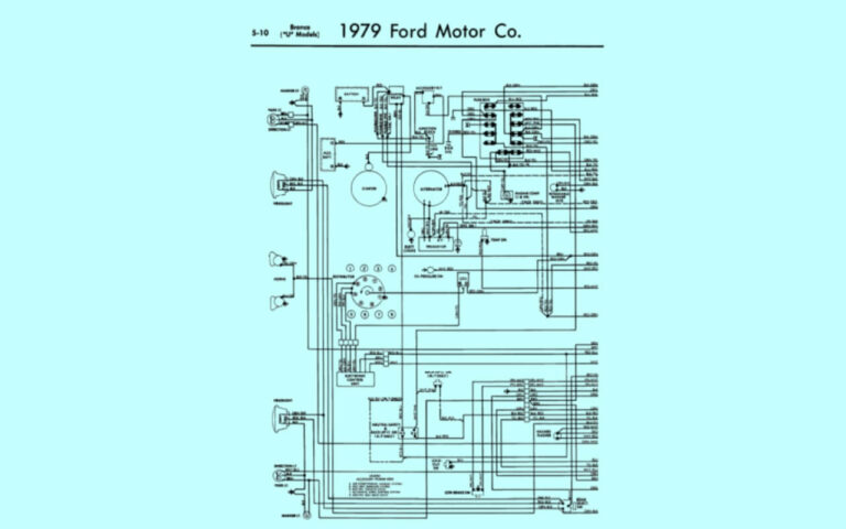
1984 F150 Wiring Diagrams
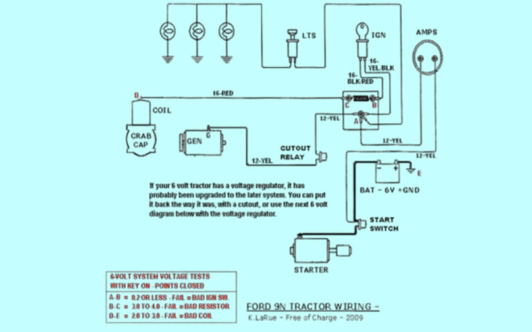
Diagram 1:
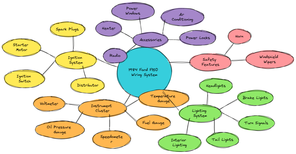
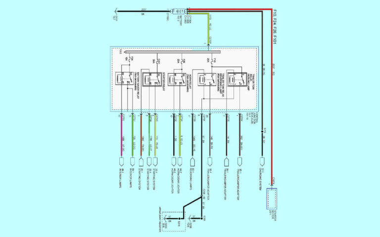
Diagram 2:
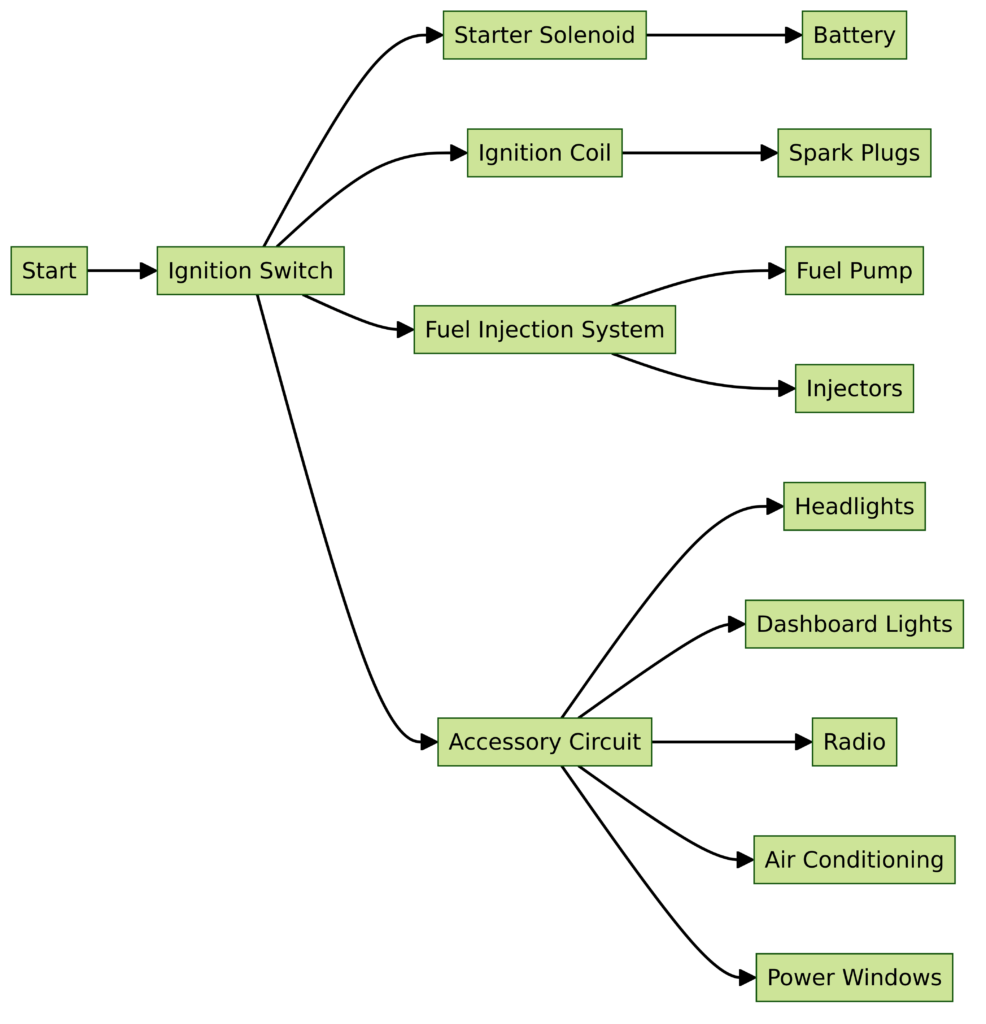
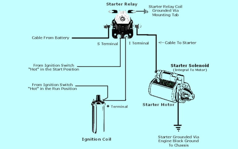
Diagram 3:
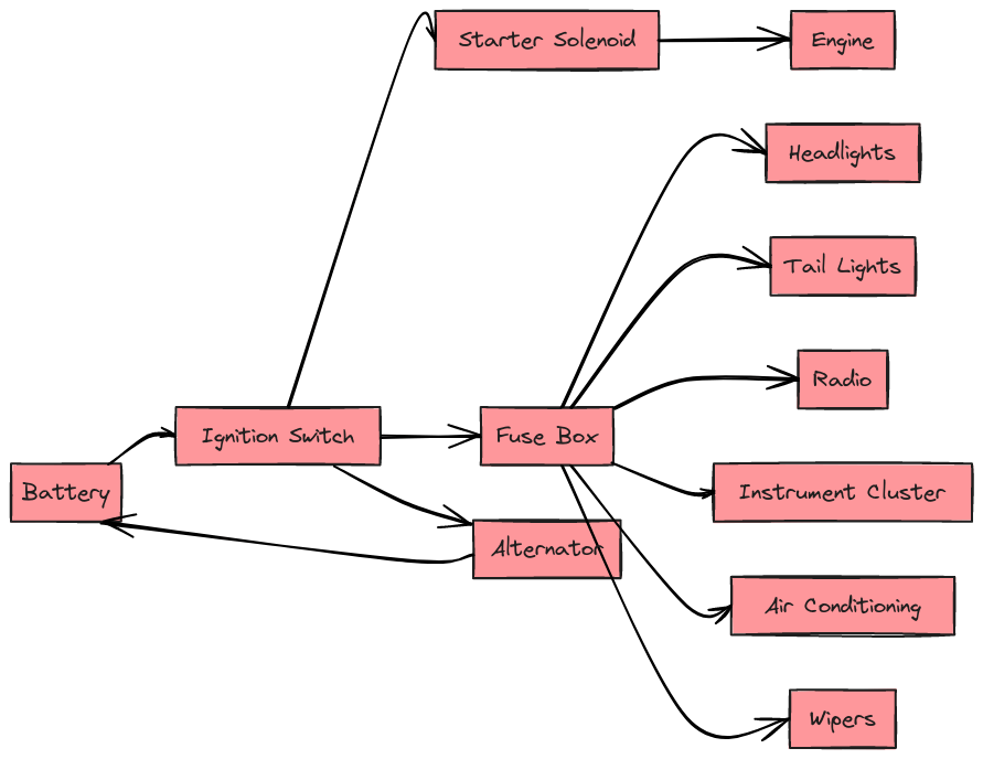
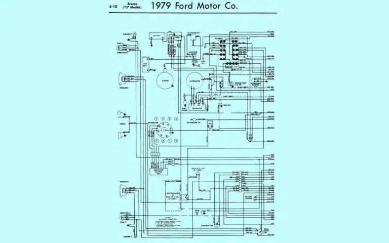
Diagram 4:

Ignition Switch, Alternator, and Charge Circuits
The foundation for getting any 34-year old truck moving is the ignition and charging systems. The ignition startup sequence begins when you insert the key into the ignition switch and turn to the RUN position. This allows current to flow to essential systems like the fuel pump, ignition module, and various engine sensors.
Turning the switch further activates the starter motor to crank the engine. During operation, a wire lead from the alternator charges the battery and powers all electrical accessories.
Reading the Wiring Diagram
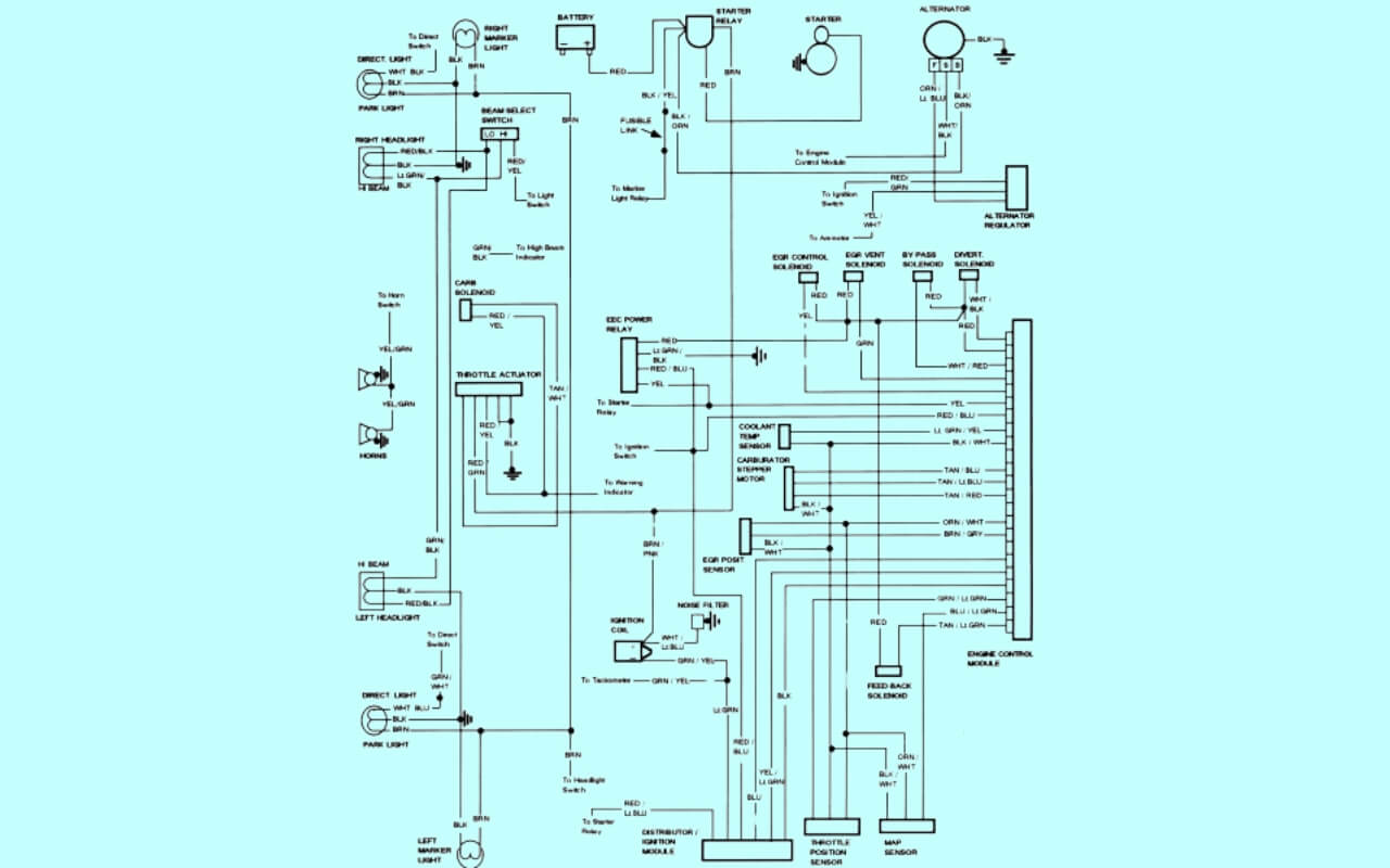
The 1984 Ford F150 wiring diagram uses color coding and numeric labels to identify each circuit wire. Here’s a quick breakdown:
- Red: Constant 12V power from the battery
- Light Blue: Switched 12V power activated by the ignition
- Dark Green: Provides ground to complete circuits
In the sample diagram above, you can see the two power sources entering the switch. When turned to RUN, power flows to the purple wire connecting to a resistor wire that acts as a safety device. Current then reaches the starter relay which cranks the engine.
Tracing and testing the wires in this manner allows swift diagnosis of switch, relay, or alternator issues that could leave your truck stranded.
Lighting Circuits Keep You Shining Bright
Aworking headlight or brake light is non-negotiable for safe road travel. Let’s examine how to use the 1984 Ford F150 wiring diagram when service is needed.
Wiring color, wire gauges, splice points and grounds are clearly marked allowing easy identification. For example, if your passenger brake light is out, you can pinpoint the issue to the light assembly, specific wire segment, connector or even a bad ground.
Circuit breakers and fuses add safety by limiting power in case of accidental shorts. Each is labeled appropriately on the diagram like “Turn Signal Fuse” and “Headlight Circuit Breaker” as shown above.
Methodically checking connections and components guided by the diagram saves hours of frustration compared to a pure guessing approach!
Interior Accessories for Comfort and Convenience
Part of the fun with a classic truck is tinkering with accessories to match modern expectations. Fortunately, the 1984 Ford F150 wiring schematic has you covered there as well. Here’s a partial snapshot:
Note the level of detail regarding fuse positions, ground locations, and splice points. Key accessories shown include:
- Cigarette lighter to power charging cables, inverters, LED interior lighting kits.
- Wiper motor and washer pump hookups.
- Flasher unit sending turn signal power to the switch.
- Blower motor resistor-wire providing lower fan speeds.
So if you want to add an OBD2 scanner or modern stereo, just tap into an accessory power circuit safely using the diagram guidance.
Pickup Bed Circuits – Lights, Power Inverters and More!
Part of maximizing your 1984 Ford F150 is taking advantage of the versatile bed for both work and play. Let’s take a look at electrical options behind the cab.
A sealed power distribution box provides hookups for:
- Interior bed lights on ignition-switched circuits
- Battery always-on power for inverters to charge gear or power tools
- Switched power to a bed mounted tool box
- Trailer wiring plug input
- Ground terminal blocks
The wiring diagram maps out the internal circuit logic so you can tap in without drilling into the vehicle cabling.
LED lighting strips can also mount under the bed rail powered safely through this integrated interface.
Navigating the Complete 1984 Ford F150 Wiring Schematic
We’ve explored specific sections of the 1984 wiring diagram to demonstrate its utility for repairs and upgrades. Now let’s discuss the complete schematic.
This master diagram compiles the entire electrical system into one densely packed presentation. Every wire segment, connector, fuse, ground and electronic module appears with precise routing info.
It may look imposing at first glance. But by applying the color coding and understanding the circuit themes above, you can gradually master the entire schematic. For example, groupings exist for:
- Engine, emission controls and onboard diagnostics
- Charging and battery supply
- Ignition, starter and distribution devices
- Lighting: Headlamps, interior, turn signals etc.
- Accessories: Heater, wipers, radio etc.
- Alarm/security systems
With some patience, the whole diagram starts making sense. And you gain confidence to tackle any electrical issue that could arise over 3000+ words!
Best Practices for Wiring Safely
Let’s wrap up with general guidelines to ensure safe repair procedures:
- Disconnect battery ground cable – Prevents accidental shorts and dangerous sparks
- Protect wire routings – Avoid pinching wires leading to damaged insulation
- Double check connections – Prevent loose leads and hazardous shorts
- Inspect firewall grommets – Seals cab from hazardous fumes
- Use proper gauged wiring – Prevents overheating and fire risk
- Double ground components – Critical for component lifespan
Follow these wiring best practices combined with the 1984 Ford F150 diagram to keep your truck running for years to come!
So in summary, while the wiring diagram may seem complex at first, learning how to read and apply it saves countless hours over your vehicle’s lifetime. We covered main systems, accessories, the full schematic overview and safe repair tips. Feel free to refer back as you service your 1984 F150 – and don’t hesitate to reach out with any questions!

