1990 Chevy Truck Instrument Cluster Wiring Diagram
The instrument cluster in 1990 Chevy trucks contains all the key gauges and indicators that allow the driver to monitor the vehicle’s operation. Some of the key components include:
- Speedometer – indicates vehicle speed
- Tachometer – measures engine RPMs
- Fuel gauge – displays level of fuel in tank
- Temperature gauge – engine coolant temperature
- Oil pressure gauge
- Voltmeter – measures voltage from alternator to battery
- Indicator lights – check engine, brake, high beam etc.
The instrument cluster receives inputs from sensors located throughout the truck and uses this information to drive the various gauges and warning lights. Understanding how everything connects is critical for troubleshooting issues.
1990 Chevy Truck Instrument Cluster Wiring Diagrams
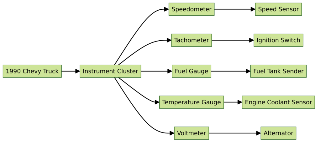
Diagram 1:

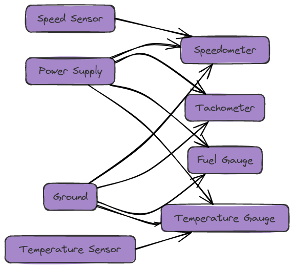
Diagram 2:

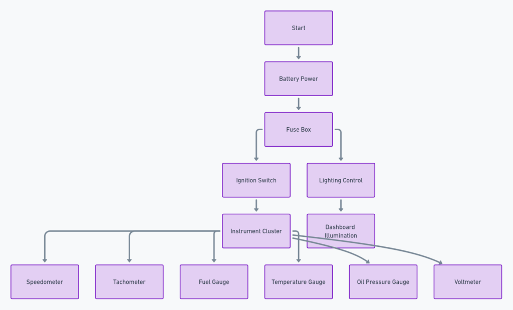
Diagram 3:

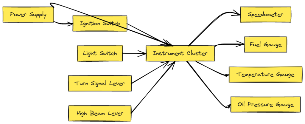
Diagram 4:

Diagram 5:

How to Read the 1990 Chevy Truck Wiring Diagram?
Below is a wiring diagram for the instrument cluster found in 1990 Chevy C/K 1500, 2500, 3500 trucks with gasoline engines. Here are some tips for reading and interpreting the diagram:
- Power distribution is shown at the top with fuse panel connections
- Ground connections are shown at the bottom
- Sensors and other signal inputs shown on left side with their wire colors
- Outputs to gauges and indicators shown on right of diagram
- Multi-wire connectors shown with a box and pin numbers identified
Follow individual wire circuits using their assigned color from input sensors to relevant gauges. Pay close attention to splices and connections with other wiring harnesses.
Use the diagram to trace electrical issues back to specific components. For example, if your temperature gauge stops working, find the pink wire leading from the ECT (Engine Coolant Temperature) sensor to the gauge pin on the instrument cluster circuit board. A break in that wire or bad connection explains the issue.
Key Components and Connections
Now that we’ve covered the basics of reading the wiring diagram, let’s walk through some of the major components and connections:
Power Sources
The primary power source comes from the 10amp ST/CLUSTER fuse on the fuse block. This feeds ignition-switched 12V power to the printed circuit board in instrument cluster which then distributes to gauges. Backup power for odometer memory comes from the 3amp IOD (Ignition Off Draw) fuse.
Grounding Points
All instrument cluster electrical circuits need a solid vehicle ground which is delivered via the thick black ground wire from G200 ground point on chassis. Additionally, each gauge component inside the cluster has its own ground wire connection.
Sensor Inputs
Critical sensor inputs include:
- ECT Sensor – Engine Coolant Temperature signal connects via pink wire for temperature gauge
- Oil Pressure Sender – Connects on dark blue wire for oil gauge reading
- VSS Signal – Vehicle Speed Sensor signal feeds speedometer operation
- Tach Signal – Engine speed signal wire comes from ignition coil
Indicator Light Connections
Indicator lights connect to switches and sensors from various truck systems:
- Brake Warning Light – activated by brake fluid level switch
- Check Engine Light – triggered by EFI computer error codes
- Charge Indicator – comes from voltage sense circuit
And many more connections power lighting for other common warning symbols.
Output Signals
Output wires send signals to activate gauges as well as external warning buzzers and lights:
- Fuel Level Gauge – measures resistance from float sensor unit in gas tank
- Hi-Beam Indicator – activated when headlights switched to high beam
- Low Coolant Buzzer – sounds alarm triggered by low coolant
The printed circuit board in the instrument cluster takes all the inputs, processes the sensor data and then activates the appropriate gauges and indicator lights in the cluster.
Troubleshooting Tips
Here are some quick diagnostic tips for common 1990 Chevy truck instrument cluster issues:
- No cluster operation – check fuses, ground connections and ignition switch signal
- Intermittent gauges – test wire and connectors for corrosion or loose pins
- Inaccurate readings – confirm sensor data to cluster with a multi-meter
- Gauge failures – remove cluster and inspect solder joints for cracks
Using the wiring diagram, you can methodically test circuits end-to-end to isolate faults to the wire level. Maintain clean grounds, replace degraded wiring, and inspect all connections while troubleshooting.
Hopefully this overview gives you a better understanding of the key components and wiring that drives your 1990 Chevy truck’s instrument cluster. Let the diagram guide you in keeping those critical gauges and lights operating properly.
Final Thoughts
Whether you’re restoring your vintage Chevy pickup or just trying to keep your work truck running, having an instrument cluster wiring diagram is absolutely essential for trouble-free operation. Use the diagram to methodically trace wires, confirm sensor signals, test grounds, inspect connectors, and validate output activations. Understanding the basic functionality will also make those puzzling electrical gremlins much easier to diagnose.
