Demystifying 1995 Chevy Silverado Wiring Diagrams: Your All-In-One Guide
So you popped the hood of your trusty 1995 Chevy Silverado and faced a maze of brightly colored wires and mysterious electrical components. Maybe your truck’s engine started acting up, the factory stereo went kaput, or you want to install some new fog lights. But troubleshooting and understanding this electrical spaghetti means deciphering those confusing wiring diagrams.
Can you really make heads or tails of those complex diagrams for your GM truck? And more importantly – do you know how to use them to fix your ride?
The answer is: yes you can! While 1995 Chevy Silverado wiring diagrams may seem intimidating at first glance, they provide invaluable information to properly diagnose and fix electrical issues. With some key tips for understanding and decoding the schematics, you’ll be able to leverage these diagrams like a pro mechanic to keep your classic Chevy pickup running smoothly.
In this comprehensive guide we’ll cover:
- What exactly wiring diagrams depict and what you can learn from them
- Why possessing the correct diagram for your full-size
Chevymatters tremendously - Where to locate the authoritative diagrams for your model year truck
- How to decipher the different symbols, colors, and connections
- Real-world examples of leveraging diagrams for common repairs and upgrades
Trust us – by the end of this article, terms like “ground lead,” “electrical connector,” and “DTC trouble code” won’t phase you in the least. So let’s get started unraveling the mystery of Silverado wiring diagrams!
1995 Chevy Silverado Wiring Diagrams
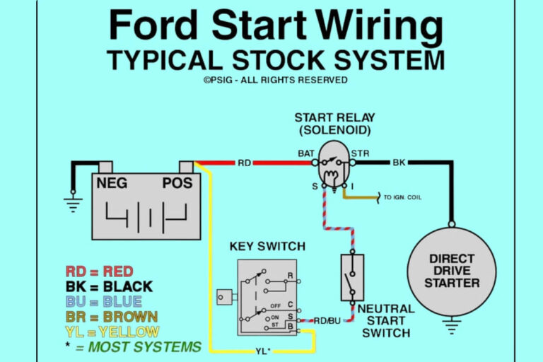
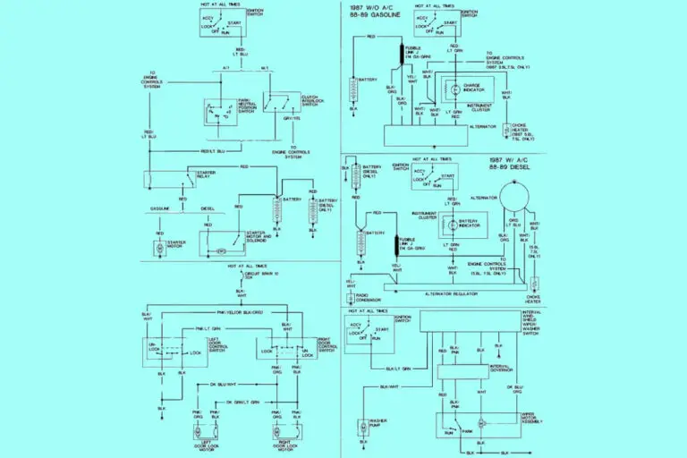
Diagram 1:
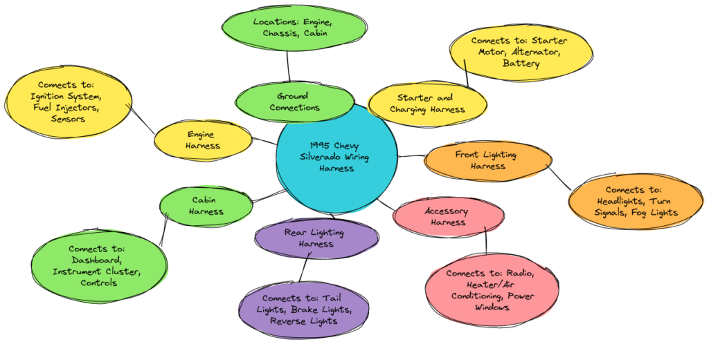
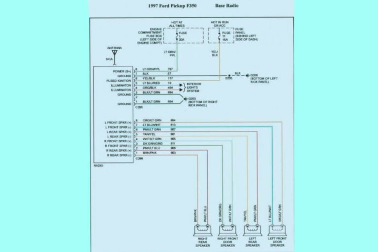
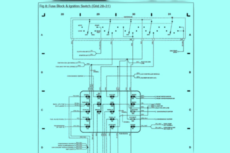
Diagram 2:
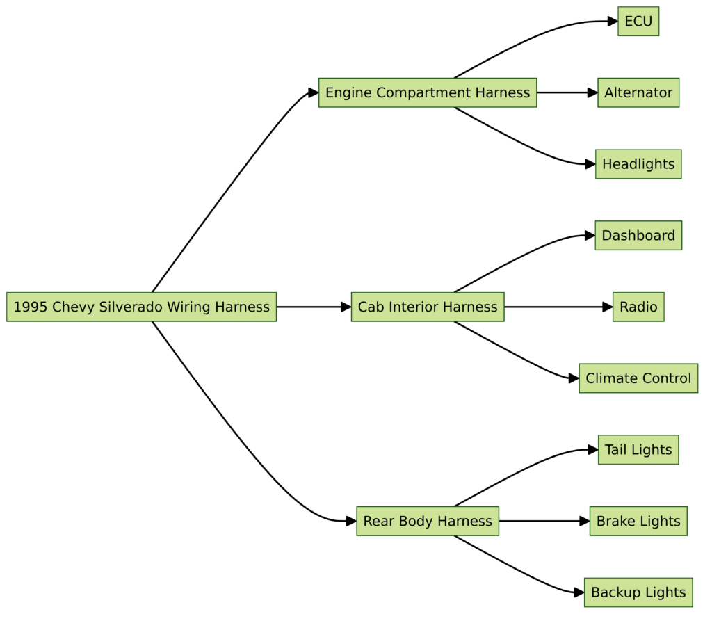
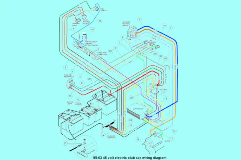
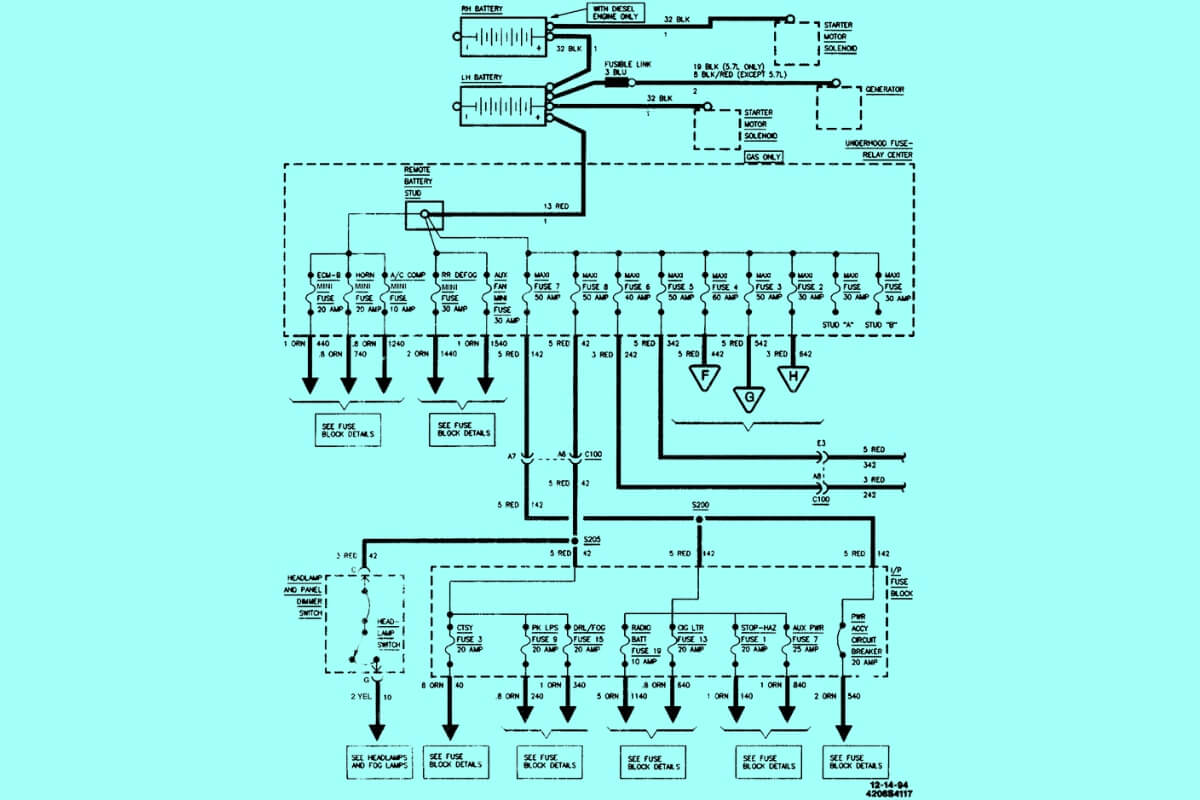
Diagram 3:
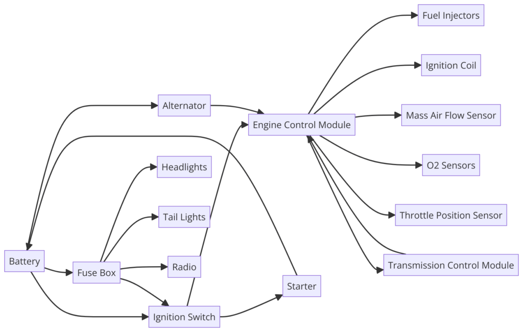
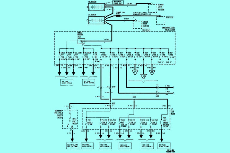
Diagram 4:
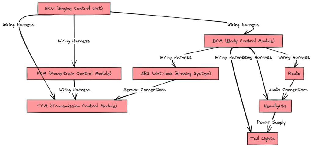
Diagram 5:
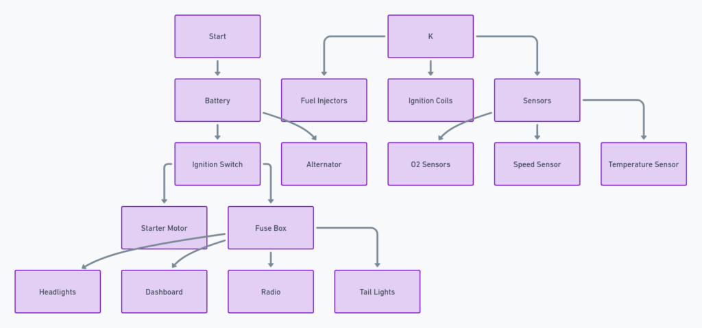
Diagram 5:

A Wiring Diagram Is Your Electrical System Roadmap
Before jumping right into tracing wires and identifying relays, we need to cover some wiring diagram basics. What exactly is a wiring diagram and why would you want to use one?
In short – a wiring diagram visually depicts the various physical connections and electrical components that make up a vehicle’s electrical system. Following the path of wires from power sources to end devices, wiring diagrams literally map out the underlying electrical infrastructure.
Think of it like a road map for mechanics – instead of highways and surface streets though, the “roads” are colorful wire traces and the “destinations” are fuses, electronic control units, switches, sensors, lights, and other electrically-powered components in your truck.
While complex diagrams can be intimidating at first glance, they lend incredible insight into system design and interaction. Studying diagrams helps you understand how electricity flows from the battery to trigger fuel injection, power windows, or make turn signals blink. They also reveal exactly where individual components live under the hood or dash.
Without access to such mapping, attempting electrical work on your aging Silverado would be shooting blindfolded. Install that new Pioneer touch screen stereo incorrectly and you could end up with serious electrical gremlins. Try fixing running light issues without diagrams and you might never solve the root cause.
Why You Need Your Specific Chevy Truck Diagrams
Now just any Silverado wiring diagram won’t do. Because subtle design tweaks distinguish the 1995 model year from 1996…which differs from the 1994 predecessor. Perhaps Chevy relocated that front trailer harness junction in 1996? Or switched relay suppliers between 95 and 96 model years?
Small variances like relocated fuse boxes, updated drive-by-wire software, or revised DTC definitions can wildly alter diagram specifics. Using inaccurate diagrams for repairs could brick an engine control module or leave you chasing ghosts for weeks.
And that Pioneer stereo expecting 12 volt switched head unit power? Hooking it to ground or constant 12V from a 1996 diagram might let the magic smoke out…along with days wasted finding that blown internal fuse.
So ensuring you obtain exact diagrams tailored to your particular Chevy Silverado‘s vintage avoids disaster. While third party manuals from Haynes and Chilton work in a pinch, factory documentation depicts reality better than assumptions some author made. Dedicated communities like GMT400.com and your local Chevy dealer provide authoritative wiring data.
In addition to verifying model year accuracy, narrow your search to engine specifics where possible. That trusty old k1500 packing GM’s bulletproof 350 (5.7L) V8 featured different sensors and emission controls than a later Vortec 5700. So diagrams dedicated to your precise displacement and engine designation prove extremely helpful.
Where To Secure Those Critical Chevy Wiring Diagrams
Alright – by now hopefully we’re clear that older truck electrical systems differ across model years…and even month of production. So where exactly should you hunt down the holy grail of accurate diagrams?
Your best bet comes from sourcing factory service manuals when available:
- Printed GM Shop Manuals with wiring diagram sections were previously available. Check eBay, Craigslist, or niche forums for second-hand copies covering the
88-98 GMT400 platform. - Some aftermarket manual publishers sell CD/DVD packs with GM wiring diagram excerpts for your truck’s year and engine. Brands like Helm make finding the right diagram less painful if money is no object.
- Consider asking nicely at your local Chevy service department – some have archives or microfiche containing diagrams. Maybe compliment that service advisor’s tie and bribe him with donuts?
If paying for factory diagrams proves difficult, the internet provides other communities eager to share OEM specifics:
- Forums like GMT400.com, CK5.com, ChevyTrucks.com, and others contain member uploads of scanned diagrams. Search for your engine, cab style, transmission, or other modifiers along with “wiring diagram pdf” as keywords. You might luck out!
- Facebook groups like “GMT 400 Truck Club” or “Chevy/GMC Truck Parts” often allow members to request wiring diagrams. While digging through comments and sparse photo tags presents another chore, success happens.
- Various individual websites host snippets of factory diagrams among blog posts and articles. Feed search engines terms like “k1500 engine diagram wire harness 1994” to uncover personal OEM archive uploads.
While these alternative sources don’t guaranteefactory-accurate diagrams tailored to your VIN, you might glean useful troubleshooting insights before shelling out for perfect documentation. At minimum they provide examples to reference while decoding unfamiliar wiring schematics!
Decoding Chevy Wiring Diagram Symbols, Lines, and Connections
Alright – with model-specific diagrams secured, it’s time to actually decipher those cryptic documents! Let’s clarify exactly what all those colors, shapes, lines, and symbols mean on typical GM truck schematics.
While appearing hopelessly complex at first glimpse, diagrams follow standardized conventions making them understandable to those willing to learn. Whether you worked on aircraft electrics or telephone switch gear, common symbology applies across industries. Once learned, you can leverage wiring diagrams for practically any vehicle!
Here’s a quick symbol decoder to clarify common wiring diagram language:
- Wires and Cabling: Solid and dashed lines show electrical connections between components. Colors indicate real wire colors, helping trace physical routing. Black usually means ground leads.
- Components: Rectangles and blocks represent electrical parts like fuses, relays, ECU modules, switches, lights, etc. They’re labeled with part names or identification numbers to lookup in repair manuals. Names describe function – like “Fuel Pump Relay Control” or “Trailer Brake Control Module.”
- Component architecture: Inputs show on diagram left sides, outputs on right. Components power sources enter from above, ground connections below. This convention mirrors real-world mounting orientations.
- Key vs Power vs Ground: Circuit function clarified by line styles. Keyed 12V power necessary for module activation differs from direct battery/alternator power fueling significant current draw.
- Connectors and plugs: Oval shapes with individual contacts labeled show how harnesses plug into various components. Matching connector views prove invaluable for splice and pinout work.
- Beyond the Basics: Numerous other symbols exist denoting fuses, grounds, specialized wiring, resistors, transistors, diodes, and more. But most repairs start by grasping basics before needing specialized schematic knowledge.
While mastery takes considerable practice, even beginners can leverage diagrams for basic tasks. Following color-coding provides immense insight during troubleshooting. Component placement guides splice and pinwork. And understand major power distribution prevents damaging electronics or power wires.
Let’s move onto real-world applications demonstrating how diagrams solve tricky problems!
Practical Applications – Let’s Fix Stuff!
We get it – eyes glazed over four paragraphs back hearing about abstract symbols and connector views. Nothing motivates like real parts in hand!
So below we walk through several common Silverado owner repairs aided tremendously by glancing at the right diagrams:
Rewiring Faulty Headlight Switch Connections
Headlights cut out intermittently despite bulb and ground checks? Before condemning that dodgy looking headlight switch near the ignition cylinder, consult the wiring diagram!
Tracing color-coded wires back from front lighting shows several upstream components possibly causing issues. Bad chassis ground straps cause weird behavior. Frequent winch use overheats light power relays when owners don’t install bypass fusing.
And assuming wires shorted inside the aged headlight switch, checking connector pinouts in the diagram helps determine failed circuits to rewire. Sometimes several pins power various light circuits!
Adding Fog Lights with Proper Switch Wiring
Love the look of yellow fog lights cutting through inclement weather? Mounting the rigid brackets and lights proves the easy part! Determining how to trigger power requires diagram consultation so you don’t overload factory switch circuits.
Typical setups use relay harnesses triggered when the headlight switch enters first detent position. But some earlier GM trucks had unique power specifications requiring new switch installation. Identify an appropriate power source like the front marker or cab clearance light circuits to avoid damaging delicate GM headlight switches.
Diagnose Elusive Tachometer Failure
Intermittent tachometer failure despite intact cables and sender signal? Dive into the cluster wiring diagram!
By diagramming the sensing wire’s path through several connectors and sleeves, you discover rubber grommets chafing the tach signal wire’s insulation. Corrosion then provides intermittent contact until stranded mid-highway at night in the rain!
Major Engine Rewiring Post-Swap
Dropping a built 350 Vortec (5.7L) into your trusty work truck requires significantly rewiring engine sensors, ignition system, and management computers. While engines share similarities on the outside, much differs behind the scenes.
Swapping older TBI systems to modern EFI requires reworking fuel control. Sensor inputs differ for engine temperature, cam position, oxygen content. And don’t dare forget upgrading alternator amperage and changing connector types!
While painstaking, a clearly laid out engine wiring diagram combined with the truck body diagram assists enormously for engine swap clarity. You’ll know exactly which new wires and sensors integrate with existing systems.
Fixing Electrical Gremlins
Intermittent issues surface across older vehicles – flakey blower fan behavior, sticky power window function, faulty 4×4 transfer case engagement.
Rather than replacing switches and motors wholesale, begin by reviewing component wiring!
Perhaps the issue relates to damaged ground straps allowing sensor interference on shared leads? Or bumpy roads vibrated power connectors slightly loose. Older trucks used more mechanical linkage and fewer automation sensors – diagrams help eliminate linkages before assuming failed modules.
We’ve walked through a few examples of how wiring diagrams prove invaluable for diagnosis and repair. While additional scenarios exist, the fundamentals remain similar – grasp the diagram basics, identify components by name, then trace connections.
In Closing – Understanding Diagrams Unlocks Repair Confidence
Hopefully this post dispelled some anxieties around 1995 Chevy Silverado wiring diagrams. While appearing hopelessly complex upon first glance, diagrams adhere to logical conventions making them incredibly useful for repairs.
Whether fixing failed lights, enhancing your truck’s capabilities via new accessories, or undoing hack jobs a previous owner cobbled together, wiring diagrams lead the way. They help trace physical wire routing, identify splice and connector locations, clarify circuit power needs, and reveal component interactions.
So stay calm and leverage diagrams when tackling your next automotive electrical project! Those cryptic shapes and colored lines hide immense insight into that beloved bowtie pickup you count on daily. Let diagrams work for you instead of intimidating from the shop manual shelf.
Soon you’ll flip to the back of those dusty manuals like a pro – casually tracing multi-colored wiring routes between pages scattered with coffee stains and greasy fingerprints. Other gearheads will think your old Chevy discussed diagrams at the local diner or bowling alley given how easily you chat about ground leads, splice packs, gauges, and DTC trouble codes over a cold one…

