Deciphering Ford’s 3 Wire Alternator Wiring Diagrams
Have you ever opened the hood of your Ford truck or tractor and just scratched your head looking at the wiring mess around the alternator? I’ve been there too. Those three wires and various terminals coming out the back of that handy electrical component can definitely be confusing.
If you’ve wondered how to properly connect a 3 wire alternator on your Ford vehicle, and what that diagram on the fuse box cover means, you’ve found the right place! Many classic Ford’s came equipped from the factory with simple 1 wire alternators. But upgrading to a modern, self-exciting 3-wire alternator and understanding the appropriate wiring diagram is crucial to get the best charging performance.
In this detailed guide, you’ll learn step-by step how to connect and troubleshoot 3 wire alternator wiring specifically on Ford vehicles. We’ll cover what each wire does, how to hook them up to the ignition, battery cables, voltage regulator, as well as tackling common wiring problems. You’ll also discover how to read those cryptic Ford alternator wiring diagrams splashed across old cracked fuse box covers.
Ready to stop scratching your head? Let’s wire that new alternator up right!
Overview of 3 Wire Alternator Function
Before jumping into the specifics on Fords, let’s quickly discuss what a 3 wire alternator is and how it differs from older external regulator models.
The typical modern alternator has three wires that connect it to the rest of the charging system components:
- Positive – The main power feed wire providing current to charge the battery
- Ground – Returns current to alternator housing/negative battery terminal
- Regulator – Allows feedback voltage signal to regulate output
Older 1 wire GM alternators have an external voltage regulator box that controls field current to regulate voltage. The external regulator died out in the 1960s as alternators with internal voltage regulators became the norm.
When you upgrade from a Ford 1-wire alternator to the 3-wire style, you are getting improved automatic voltage regulation without having to wire in an external regulator box. But the 3 wires must be properly connected for this self-exciting regulator to work!
Ford’s 3 Wire Alternator Wiring Diagrams
Diagram 1:

Diagram 2:

Diagram 3:

Diagram 4:

Diagram 5:

Advantages of a Ford 3 Wire Alternator
The 3rd wire in those “3 wire alternators” might seem complicated but offers big advantages:
More steady charging – Voltage won’t fluctuate as engine RPMs change
Fits standard mounting – Bolts right up to Ford brackets designed for external regulator models
Automatic voltage control – No tweaking a regulator box knob to set voltage
Flexible wiring – Can utilize original Ford wiring or custom installation
In a nutshell, adding a modern 3 wire alternator to your older Ford gives you better charging and easier installation!
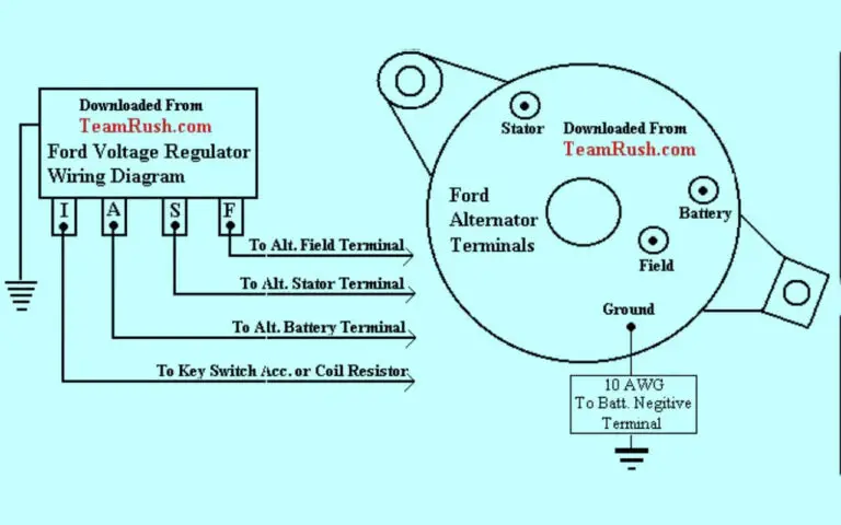
Breaking Down Ford 3 Wire Alternator Wiring Terminals
Here is a quick overview of each of the three wires coming out the back of a typical Ford 3-wire alternator and where they need to connect:
Alternator Output Terminal
This large terminal connects to heavy gauge positive cable supplying current from the alternator. Typically a large gauged braided wire secured with a large nut/bolt. Often stud-mounted rather than push-in style spade connector.
Voltage Regulator Connection
The regulator wiring is the key that allows the smart self-exciting alternator to automatically adjust output based on vehicle demand. Typically a single small 14 or 16 AWG wire with spade push-on connector.
Alternator Ground Strap
Secures the alternator housing to vehicle ground, completing the circuit path for proper alternator function. Usually 14 or 12 AWG wire with spade/ring terminal connector.
OEM setups often have a braided ground strap that is bolted on one end to rear Alternator housing. The other end secures to a true chassis ground point.
That’s the basics on what each wire needs to connect to. Now let’s look at the overall wiring setup on a typical Ford vehicle!
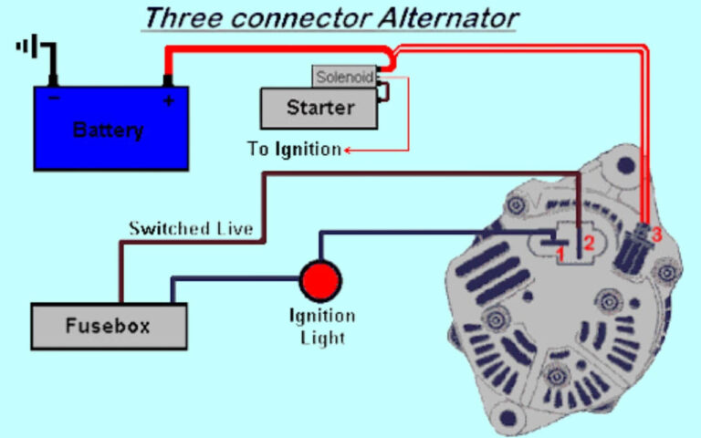
How Fords Wire 3 Wire Alternators
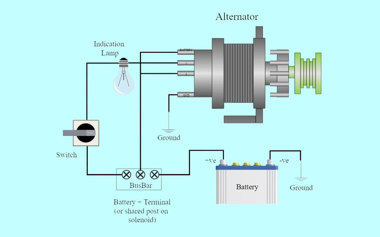
Focusing just on the connections at the actual alternator, here is how Ford typically wires their charging system:
The heavy positive charge cable runs from alternator main stud output terminal to the positive battery post. This handles all the charging current.
The smaller 14 AWG voltage regulator wire splices into the ignition wire that energizes the dashboard warning light. This provides key-on power to the voltage regulator.
The ground strap or wire connects the rear alternator housing to the vehicle’s chassis or engine block, completing the ground circuit.
There are two key aspects of this standard Ford setup:
1. Voltage regulator wire taps into ignition circuit: This provides power to the regulator only when ignition key is turned on. This allows the alternator to energize and start charging.
2. Warning light is wired into same circuit: The dashboard charge indicator light comes on with key-on power, alerting the driver if there is a charging issue. The light goes out when engine starts and alternator starts charging properly.
This simple yet clever wiring allows the existing warning lamp circuit to provide ignition-switched power to a modern 3 wire alternator so it can self-excite and self-regulate!
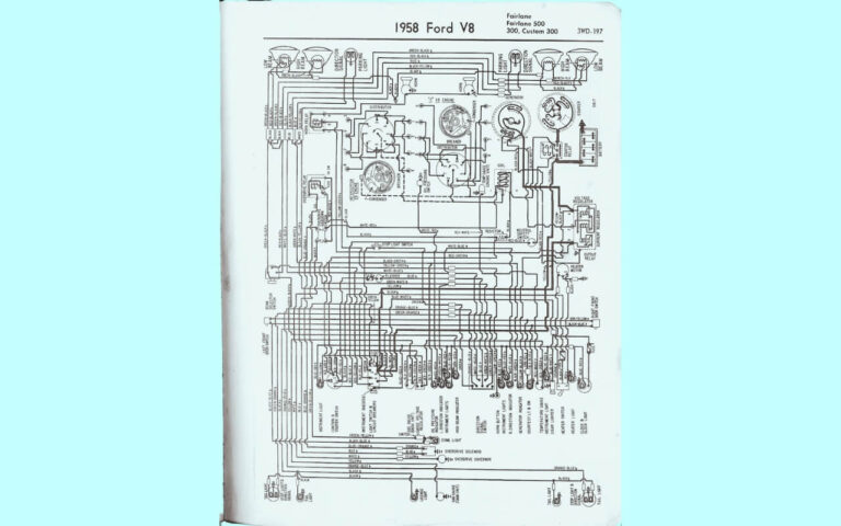
Older Ford Alternator Wiring Diagram Basics
If you have an older Ford vehicle, you’ll need to hook up the 3 wire alternator to match the original wiring diagram. Let’s cover the basics of understanding these old diagrams:
Wire Colors – Ford typically uses standardized colors:
- Red – Positive Battery Feed
- Light Blue or Black – Ground wire
- Dark Blue – Voltage Regulator wire
Numbers & Letters – These indicate connectors and components. For example “A3” means the #3 pin on alternator regulator plug.
Warning Lamp – The light bulb icon represents the dashboard “idiot light”
Other Symbols – Indicates splices (dots), grounds (vertical bars), key switches, etc.
So in summary, the cryptic diagram is showing connections from alternator back through the warning lamp into the ignition circuit.
Armed with that background, let’s move on to wiring specifics!
Step-by-Step Ford 3 Wire Alternator Wiring
Let’s walk through connecting that shiny new 3 wire alternator on your Ford:
Prep Work
Complete any needed modification or adaptation of original wiring before bolting the alternator on. Extend or replace wires that may be too short or damaged to reach new alternator wiring terminals.
Mount Alternator
Physically mount replacement 3 wire alternator using correct brackets and alignment. Include any needed spacers or adjustments so pulley and belt line up properly with other components.
Ground Strap
Connect ground strap ring terminal securely onto alternator housing grounding tab, then connect other end to known good ground source point. Ensure full metal-to-metal contact for solid ground.
Main Output Stud
Attach primary thick positive charge wire to large output stud terminal on rear of alternator. Red wire typically in Ford applications. Make sure connection is extremely tight and secure.
Voltage Regulator Wire
Connect a new length of 14 AWG wire to spade push-on terminal, route wire cleanly through engine compartment, inserting through any protective loom or tape at contact points. Finally “T-splice” it into the original Ford voltage regulator ignition circuit wire. This energizes the regulator when key is turned on.
Battery Cable
Connect positive battery cable to same alternator output stud as main charge wire. Check for corrosion at both ends, tighten securely.
Verify Wiring
Double check that ALL connections are tight with good metal contact. Ground and power circuit wires visually intact with no risk of rubbing/chafing. Proper splice joins in any spliced wiring — no exposed copper visible.
You now have a completed charging system and can re-install any protective engine covers removed.
Let’s move on to diagnosing and troubleshooting now!
Troubleshooting Ford 3 Wire Alternator Wiring
If you completed the 3 wire alternator installation steps but still have charging issues or warning lights, some key things to check:
Warning Light – Should illuminate when ignition is first turned on, then goes out shortly after engine starts as alternator begins charging.
Bad Ground – Corroded or loose ground strap connection points can cause all kinds of charging gremlins.
Voltage Reading – Use a multimeter at battery terminals to check for ~13.5-14.5V charge after vehicle has run for 15+ minutes. If low/no charge, begin deeper diagnosis.
Alternator Output – Use voltmeter to test power directly at alternator large output stud. If no voltage during charging, the alternator itself has likely failed.
Fuse/Fusible Link – The feed wire for the regulator and indicator light is usually protected by either a fuse or fusible link wire. Visual check and test for continuity.
Wiring issues can definitely be frustrating to diagnose. Taking the time to thoroughly check connections and wire continuity/resistance is always wise before condemning the expensive alternator component!
Ford-Specific Alternator Tips
Over years of working on Fords, I’ve compiled some additional tips just for wiring Ford alternators:
F-Series Trucks – Check that voltage regulator wire splices into brown wire leading to small “S” spade terminal on rear of truck alternator.
Old Tractors – Extend regulator wire along chassis frame rail, use protective loom wrap. Provide maximum slack near brushes to avoid breaking wire over years.
Upgrading 1 Wire – When converting an old external regulator setup to modern internal regulator alternator, ignore old regulator box and simply connect new regulator wire as described above. The voltage regulator takes care of the rest!
Adding Missing 3rd Wire – Many older Fords didn’t even have the regulator wire in place. Use 14 AWG and splice into any ignition circuit wire that sees power in key-on “Run” position.
Hopefully these Ford-specific alternator wiring tips help with your project! Now let’s review some common questions.
Frequently Asked 3 Wire Alternator Wiring Questions
Here are answers to some of the most common questions Ford owners have about wiring 3 wire alternators:
What’s causing my new alternator to not charge?
- Faulty wire splice connection
- Loose ground strap
- Bad fuse/fusible link
Why does my warning light stay on with new alternator installed?
- Faulty alternator self-exciting circuit
- Bad dashboard indicator bulb
- Missing or disconnected wire from warning lamp terminal
Is thicker wire better on the Ford voltage regulator circuit?
- No, should use 14-16 AWG wire gauge as specified by Ford
- Thicker 10-12 AWG can prevent proper voltage signal
Can I leave an old external regulator box wired up?
- When converting to internal regulator alternator, yes but disable old regulator by removing fusible link wire
- The external regulator will simply be bypassed
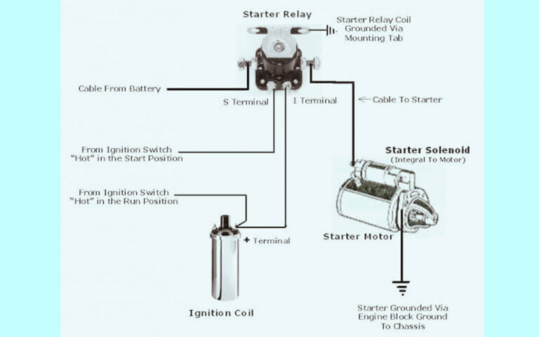
What Ford starter relay does the voltage regulator wire connect to?
- Ford doesn’t use an actual starter relay for alternator wiring
- The regulator taps into ignition switch circuit that also feeds indicator light
In Closing – Confidently Wire That New Alternator!
If you made it this far – congratulations and thanks for reading!
Let’s wrap things up with a quick alternator wiring checklist:
- Ground Strap – Solid chassis contact
- Output Terminal – Heavy gauge wire, extremely tight
- Regulator Wire – Clean 14 AWG splice into ignition circuit
- Verify Wiring – Double check grounds, splices, insulation
Follow that checklist and your new 3 wire alternator will be providing solid charging performance for years to come!
Now you can confidently install a modern replacement alternator on your Ford vehicle. And while scribbly wiring diagrams, faded fuses boxes, and crusty electrical connectors might still make you scratch your head, you can smile knowing exactly how to hook up those 3 wires.
Happy wrenching!

