Demystifying 3 Wire Ford Alternator Regulator Wiring Diagrams
Have you ever opened the hood of your Ford truck and stared at the mess of wires connected to the alternator, wondering what exactly is going on? When problems arise with the charging system, grasping the correct wiring diagram is key to diagnosing and solving issues. But deciphering these complicated diagrams can be an exercise in frustration.
This guide will walk through the purpose and function of the different wires in 3 wire alternator setups found on many Ford vehicles. With a solid understanding of how to read and use the wiring diagram for your specific vehicle, you’ll be equipped to troubleshoot charging issues, install a new voltage regulator or alternator, and keep your vehicle’s electrical system in top shape.
So what exactly is a 3 wire alternator and how does the wiring diagram help you keep your Ford on the road?
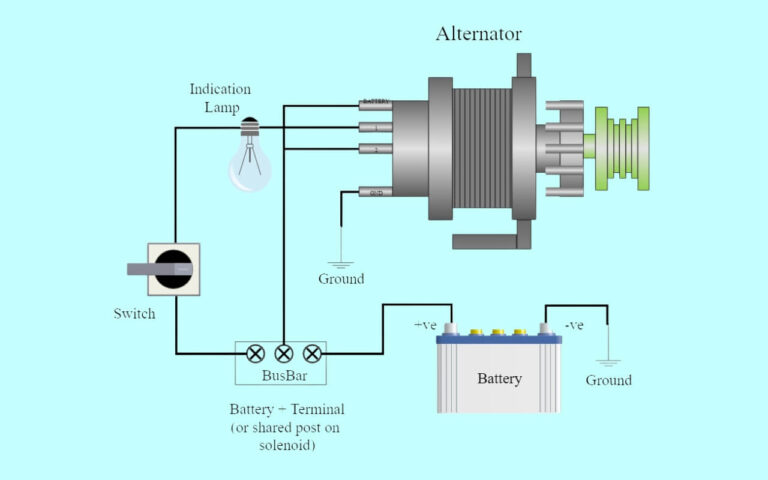
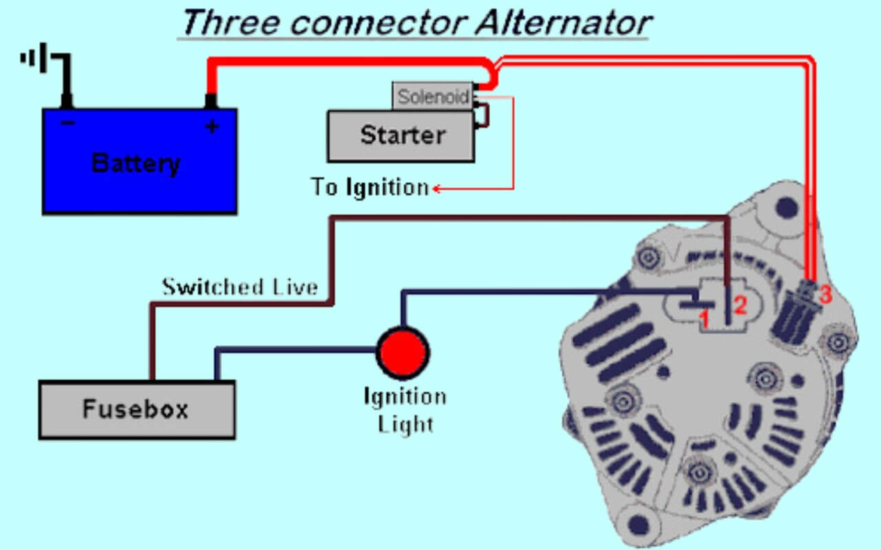
A 3 wire alternator has three main wire connections that handle the flow of voltage and current to charge the battery and power the vehicle’s electrical components. The wiring diagram visually outlines these connections – the ignition, voltage sensing, and output wires – along with the component locations and intra-system flow.
This guide will cover the following topics in detail:
- The function of each component in a 3 wire alternator wiring diagram
- How to interpret the diagram layout and symbols
- Using the diagram to diagnose and solve charging issues
- Complete steps for safely installing a new alternator
- Preventative maintenance for maximizing alternator lifespan
Understanding the Role of the Alternator Voltage Regulator
The alternator voltage regulator is the brain of your entire charging system. This component monitors your battery’s charge level and adjusts the alternator’s output to maintain the proper system voltage.
Without a properly working regulator, the alternator has no control and will overcharge the battery. The subsequent overheating can lead to premature alternator failure and potential damage.
Both external and internal voltage regulators are commonly used, with the alternator’s wiring diagram differing slightly between set-ups. On external regulator configurations, a multi-wired harness connects directly from the regulator to the alternator. This guide will focus specifically on diagrams for the internal regulator design.
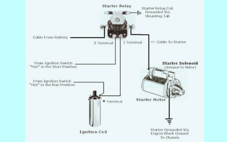
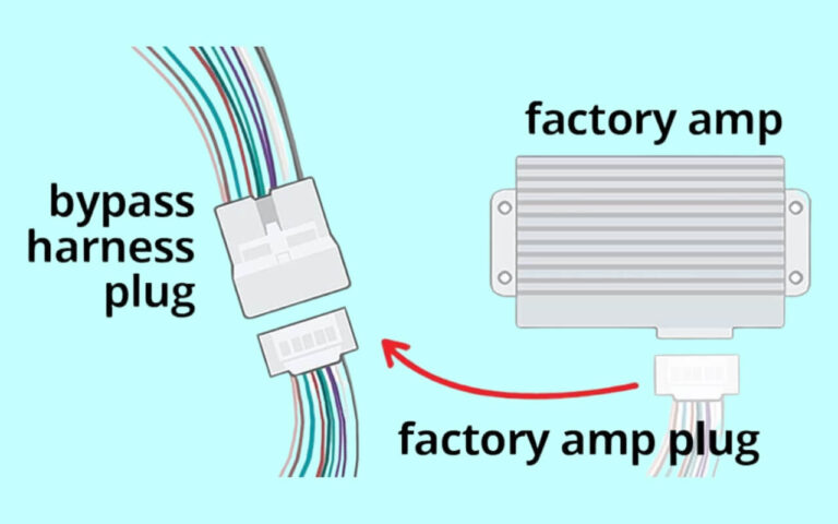
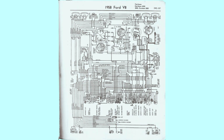
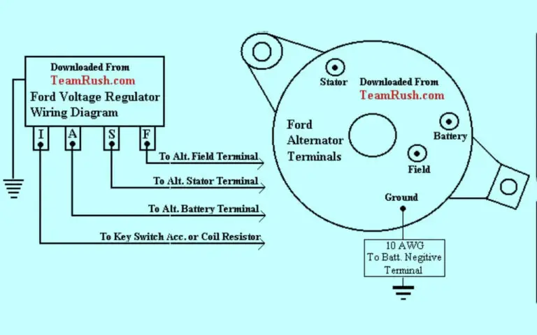
3 Wire Ford Alternator Regulator Wiring Diagrams
Diagram 1:

Diagram 2:

Diagram 3:

Diagram 4:

Identifying the Key Components of 3 Wire Alternator Systems
Alternator
The alternator is composed of wire windings surrounded by stationary magnets which generate alternating current. This AC output is converted by diodes into the DC electricity used to power your vehicle and recharge the battery. The back casing contains the regulator and brush system.
Voltage Regulator As outlined above, this component monitors voltage levels and adjusts alternator output accordingly. The regulator ensures optimal charging without over-voltaging.
Wires
The 3 wires connecting the alternator to the vehicle’s electrical system carry specific types of current:
Sensing Wire – Sends information on battery voltage level to the regulator which then adjusts output appropriately. Typically a thin yellow wire.
Ignition Wire – Provides switched power from the ignition system when key is turned on. Often red in color.
Output Wire – Carries high amperage current from alternator to charge battery and power vehicle. Frequently a very thick red wire or part of wiring harness.
Other Components
Connector – Joins alternator wiring harness to main harness on vehicle. Allows easy disconnect.
Solenoid – Receives ignition wire signal and enables battery connection to starter motor.
Battery – Provides initial power to ignition system. Then is recharged by alternator output.
Fusible Links – Protect wires by “melting” during high current situations. Act as a fuse specific to charging circuits.
Reading a Basic 3 Wire Alternator Wiring Diagram
While diagrams vary across Ford engine configurations and model years, diagram conventions remain fairly consistent. Understanding the standard symbols and layout will allow you to navigate any 3 wire alternator diagram with confidence.
Note wire locations, colors and connection points as they relate to physical components under the hood. Tracing the run of each wire clarifies the interrelated voltage flows critical to proper charging system operation.
Common Symbols
- Alternator – Represents the physical alternator component with schematic depictions of internal regulators, diodes, fans, brushes and wiring hookups.
- Wires – Colored lines indicate wire type with abbreviations like “Bat” for battery connections. Bolder lines signify heavier gauge wiring.
- Fusible Links – Fuse symbols depicting wire protection points.
- Connection Points – Squares and circles marking wire intersections or component plugs.
Flow and Function
The diagrams display the direction of current flow with arrows tracking the switching on and activation process initiated by turning the ignition key.
This visual mapping allows you to follow the voltage as the initial battery supply activates key components, which then allows the alternator to receive an exciter signal and output charging current to the battery.
Being able to interpret this sequencing empowers accurate troubleshooting when issues arise.
Using the Correct Diagram for Your Ford
Since alternator wires, components and wiring configurations vary widely across Ford models and years, it is critical to obtain and use the diagram specific to your make, model and year.
While many forums and tutorials display diagrams from random vehicles as general examples, these may differ from your required set-up and lead to errors. Always acquire the correct reference materials for your particular vehicle before swapping parts or attempting diagnostic testing.
Typical Charging Problems Diagnosed via Wiring Diagrams
If you’ve noticed warning lights flickering, a low battery condition, or total electrical failure with no charging taking place, utilizing the appropriate wiring diagram during diagnosis is a must.
No Charge to Battery
A totally dead battery that is not being recharged points to issues like:
- Faulty alternator
- Failed voltage regulator
- Wiring disconnections
- Blown fusible links
Overcharging Battery Smelling burnt rubber or seeing a very high voltage meter reading could indicate:
- Stuck or malfunctioning voltage regulator
- Regulator set point too high
- Alternator producing excessively high unchecked output
Inconsistent Voltage Output
If lights dim at idle but brighten as RPMs increase, or voltage fluctuates severely, potential culprits may be:
- Fraying or disconnected wiring
- Slipping belts decreasing alternator speed
- Sulfated or worn out battery no longer holding a charge
Flickering Lights Dashboard displays flashing along with head and interior light oscillation can be caused by:
- Defective diodes in alternator
- Ground wire corrosion
- Load demand exceeding alternator output capacity
Notice how each fault points to a different component root cause. Without proper system knowledge, attempts at remedy could be completely fruitless or only provide temporary fixes.
Accurate identification of the real issue is the key first step toward charging system restoration.
Step-by-Step Diagnosis with Wiring Diagrams
While advanced diagnostic computer scanners useful in identifying issues, technicians still employ basic voltage, resistance and continuity testing to troubleshoot. Let’s walk through a universal step-by-step process for chasing voltage flows through your 3 wire system.
Step 1
Consult wiring diagram and components layout under hood to understand system fundamentals for your particular vehicle.
Step 2
With ignition off and keys removed, check for corrosion, damage, wear on wiring, connectors and components like the alternator and battery. Tighten loose connections and clean as needed.
Step 3
Reviewing diagram for sensing wire location, back probe with multimeter set to voltage mode. Ignition on, engine off. Should read battery voltage around 12.5 volts.
Step 4
Verify ignition wire voltage at switched 12+ volts, then crank engine and check output wire for 13-14 volt reading. If battery light illuminates or voltage outside specifications, issues exist.
Step 5
Employ diagram throughout remaining diagnosis, utilizing known-good voltage values for your particular vehicle and testing wires for continuity or drops across components.
Following this protocol with diagram in hand avoids overlooking key pathways and efficiently confirms if alternator, regulator and wiring are functioning properly. before condemning components as failed.
Step-By-Step 3 Wire Alternator Installation Instructions
Once the decision is made to install new or upgraded alternator components, again referencing the vehicle-specific wiring diagram is mandatory throughout the process.
Step 1
Review installation documentation and rest with keys out of ignition. Disconnect negative battery cable first, then positive cable.
Step 2
Compare your existing alternator connector and wire routing to new replacement unit. Note variations.
Step 3
If utilizing original connector, remove by squeezing release tab and disconnecting. Transfer to new alternator.
Step 4 Check condition of all wiring. Replace connectors or wire endings as needed. Confirm accurate wire routing before terminal installation.
Step 5
Secure new alternator on brackets, install serpentine belt and ensure proper pulley alignments.
Step 6 Using diagram, connect wiring harness to alternator plugs or terminals. Confirm ignition, sensing and outputs wires are correctly positioned.
Step 7
Reconnect positive then negative battery cables. Start engine and test operation. Check voltage levels on all wires.
Employing your Ford’s correct alternator wiring diagram ensures all replacement components integrate safely and effectively. Missing this vital step risks damaging new parts and ongoing electrical gremlins.
Extending 3 Wire Alternator Lifespan through Maintenance
Like all electromechanical components underhood, alternators have finite life expectancies. That said, prudent maintenance can maximize lifespan. Here are key factors to proactively address:
Proper Battery Care
A failing battery stresses the charging system. Check terminals and clean any corrosion buildup to minimize resistance. Consider replacing battery around 5-year mark depending on your climate.
Belt Tension and Condition
Inspect belts for cracking or severe wear which could indicate impending failure. Verify belts are tensioned to factory spec to prevent alternator slippage.
Voltage Set Point
Using wiring diagram, employ a multimeter to check set point or have it set to your battery’s optimal charging voltage by a repair shop.
Connection Integrity
Loose ground straps, terminals and plugs introduce resistance and hinder flow. Tighten down or replace damaged connectors.
Regulator Brushes
Expected to eventually wear, have brushes inspected at tune-ups and swap as needed to avoid over-stressing windings.
While no amount of care can fully prevent eventual failure, deliberate care maximizes the return on your alternator investment.
Potential Issues Beyond Actual Alternator Malfunctions
Charging problems incorrectly blamed on a bad alternator or voltage regulator are frequently caused by ancillary issues. Before condemning either as failed, always confirm:
Electrical Connectors
Corroded or loose connectors anywhere in system decrease critical voltage flows. Severe build up increases resistance which impedes charging.
Fusible Links
Designed to “melt” as protective fuses, blown fusible links totally interrupt necessary current. Links can blow over time or during large electrical spikes.
Parasitic Draws
If an interior light, accessory or even tuning device remains powered on when ignition is off, batteries slowly drain – sometimes to the point batteries will no longer start vehicles. This resembles charging system issues.
When electrical problems arise, never assume the root cause without verification. Methodically test wires, links and connections to isolate the actual fault.
Helpful Resources for Further Learning
Hopefully this guide has illuminated how to read and leverage 3 wire alternator wiring diagrams to keep you Ford’s electrical system running optimally. Here are additional resources to expand your charging system knowledge:
Top blog posts:
- How to Test Your Ford’s Alternator in Under 5 Minutes https://www.wikihow.com/Check-an-Alternator
- Symptoms of a Failing Alternator in Ford Vehicles https://www.atchinson.net/5-signs-your-ford-needs-an-alternator-repair/
- How Long Do Ford Alternators Last? with Maintenance Tips https://carfromjapan.com/article/car-maintenance/how-long-do-alternators-last/
YouTube videos:
- Ford Alternator Diagnosis and Replacement – Step-by-Step Guide
- Reading and Understanding Alternator Wiring Diagrams
- How to Wire a Ford Muscle Car Alternator (302 Engine Swap Basics)
Key Takeaways
- 3 wire alternators utilize three key wires to control charging current – ignition, sensing and output
- The regulator adjusts output based on voltage signals from the sensing wire
- Wiring diagrams vary by Ford vehicle make, model and year. Use the correct one!
- Diagrams allow systematic diagnosis of overcharge, undercharge and electrical faults
- Step-by-step installation instructions ensure solid connections
- Protect your investment with preventative maintenance
Understanding exactly what’s happening inside that wiring rats nest under the hood pays big dividends when your Ford’s electrical system starts acting up. Spending some time learning to navigate 3 wire alternator wiring diagrams leads to more accurate troubleshooting, smarter component installations and longer alternator lifespan.
So grab the correct diagram for your ride and unlock the visual roadmap to keeping your truck charged up and running smoothly for years to come!

