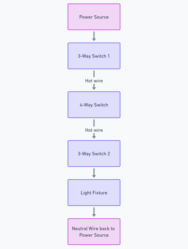
4-Way Switch Wiring Diagram
A 4-way switch is a type of electrical switch used in residential and commercial settings to control a single light fixture or other electrical device from multiple locations. The 4-way switch wiring diagram is a crucial tool for understanding how these switches work and how to properly install or troubleshoot them. In this comprehensive guide, we’ll explore the key components of a 4-way switch diagram and provide step-by-step instructions on how to read and understand this essential electrical diagram.
What’s Included in a 4-Way Switch Wiring Diagram?
A 4-way switch wiring diagram typically includes the following elements:
- Power source (usually a circuit breaker or fuse)
- Light fixture or electrical device being controlled
- 4-way switch
- 3-way switches (two of them)
- Electrical wiring, including hot, neutral, and ground conductors
These components work together to allow for the control of a single light or electrical device from multiple locations, making it a versatile and convenient solution for many home and commercial applications.
4 Way Switch Wiring Diagrams
Diagram 1:

Diagram 2:

Diagram 3:

Diagram 4:

How to Read a 4-Way Switch Wiring Diagram
Reading a 4-way switch wiring diagram can seem daunting at first, but with a bit of understanding, it becomes quite straightforward. Here’s a step-by-step guide:
- Identify the power source: Locate the circuit breaker or fuse that provides power to the circuit.
- Trace the hot wire: Follow the hot (black) wire from the power source to the light fixture or electrical device being controlled.
- Locate the 4-way switch: Find the 4-way switch in the diagram, which is typically represented by a symbol with four terminals.
- Identify the 3-way switches: Locate the two 3-way switches, which are used to control the power to the light or device from multiple locations.
- Follow the wiring connections: Observe how the hot, neutral, and ground wires are connected between the power source, 4-way switch, 3-way switches, and the light or device.
By understanding these key elements, you’ll be able to effectively read and interpret a 4-way switch wiring diagram, making it easier to install, troubleshoot, or modify your electrical system.
Additional Considerations
When working with a 4-way switch wiring diagram, there are a few additional factors to keep in mind:
- Proper grounding: Ensure that all ground wires are properly connected to ensure the safety and proper functioning of the electrical system.
- Wire color conventions: In the United States, the standard wire color conventions are black for hot, white for neutral, and green or bare copper for ground.
- Switch location: The placement of the 4-way and 3-way switches can vary, so it’s essential to follow the diagram to ensure the proper installation.
- Electrical safety: Always turn off the power at the circuit breaker or fuse before working on any electrical project, and follow all local electrical codes and safety guidelines.
By understanding these additional considerations, you can confidently work with 4-way switch wiring diagrams and ensure the safe and effective installation or troubleshooting of your electrical system.
Conclusion
The 4-way switch wiring diagram is a essential tool for understanding and working with this type of electrical switch. By familiarizing yourself with the key components, learning how to read the diagram, and keeping safety in mind, you can confidently tackle 4-way switch installation, modification, or troubleshooting projects. Whether you’re a homeowner, electrician, or DIY enthusiast, this comprehensive guide will help you navigate the world of 4-way switch wiring with ease.


