4 Wire Trailer Wiring Diagram – An Easy Visual Guide
Whether you just bought a trailer or looking to troubleshoot issues with an existing one, understanding the trailer wiring diagram is essential. Specifically, the 4-wire system standardizes connections for trailers to tow vehicles, providing a simple yet effective way to power trailer lights and charge batteries.
If you’re asking “how to read a 4 wire trailer wiring diagram?” or need a refresher, this beginner’s guide breaks it down for you. Read on to learn about:
4 Wire Trailer Wiring Diagrams
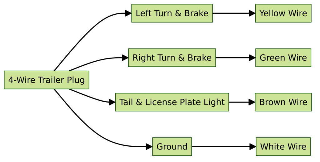
Diagram 1:

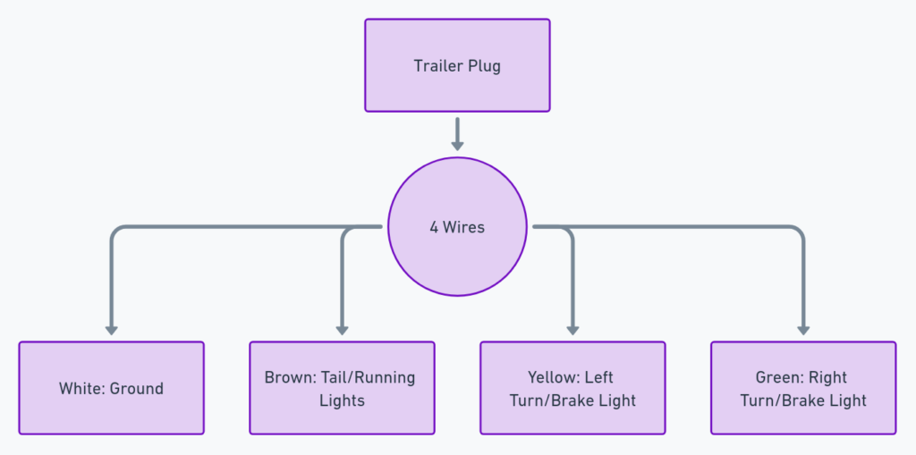
Diagram 2:

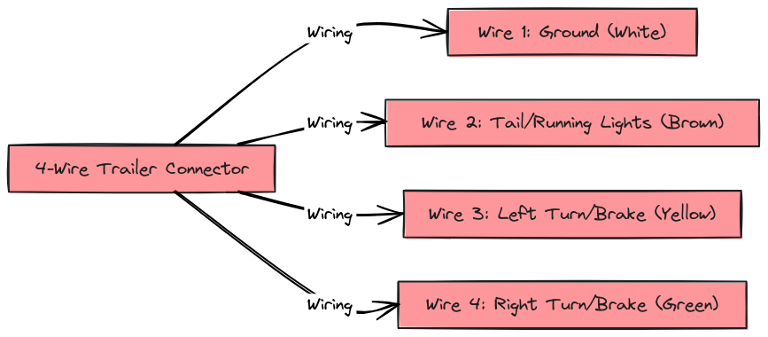
Diagram 3:

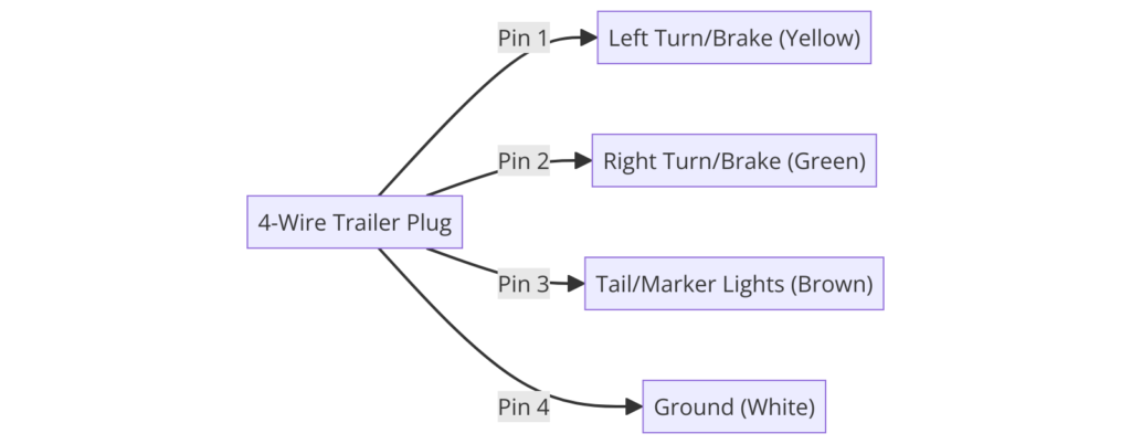
Diagram 4:

Diagram 5:

What’s Included in a 4 Wire Trailer Wiring System
A 4-wire trailer wiring system is the standard for most trailers. It contains:
- Power – Provides 12V power from the tow vehicle’s battery to charge the trailer battery. Typically a white wire.
- Ground – Gives a common ground reference between the tow vehicle and trailer. Often a brown wire.
- Left turn/Brake – Powers the left trailer turn signal and brake lights when activated. Usually a yellow wire.
- Right turn/Brake – Powers the right trailer turn signal and brake lights when activated. Often a green wire.
How to Read the Diagram
Here are some tips:
- Wires color coordinate between the 4 wire trailer plug and vehicle plug.
- Arrows indicate current flow direction. They point away from power sources.
- Parts with key codes or outlines on both trailer and tow vehicle match up.
- Check connectors to identify pins for wires entering/exiting them.
Let’s examine a standard 4-wire trailer wiring diagram.
The top shows the trailer side with a 4-pin connector. The front pin powers the trailer battery through the white ground wire. The left pins connect to turn/brake lights.
The bottom shows the tow vehicle side with a 4-pin connector. The left pin provides battery power. The right pins individually activate the left/right trailer turn/brake lights when tow vehicle signals or brakes are engaged. They return through a shared ground pin.
As you can see, by reading wiring directions, matching colors, and checking connectors you can get a basic understanding of the electrical circuits in a 4-wire system.
Final Thoughts
Trailer wiring can seem complicated at first glance. But most systems follow a standard 4-wire setup. Learning to interpret the trailer wiring diagram gives you knowledge to troubleshoot issues or install new lights.
The main takeaways:
- A 4-wire system handles basic lighting and battery charging.
- Color coded wires must match between trailer and vehicle plugs
- Understanding how current flows through wires makes diagram “roads” logical to follow
With some focused reading, you’ll gain confidence in being able to say “yes I can read that trailer wiring diagram!” This empowers you to handle more RV repairs and upgrades yourself.
Hopefully you now have a better understanding of 4 wire trailer wiring diagrams. Let me know if you have any other questions!
