5.3 Vortec Engine Wiring Harness Diagram
The 5.3 Vortec engine is a popular choice among automotive enthusiasts and mechanics alike, known for its reliability and power. At the heart of this engine lies a complex wiring harness, responsible for transmitting crucial electrical signals and ensuring the seamless operation of various components. In this comprehensive guide, we will delve into the intricacies of the 5.3 Vortec engine wiring harness diagram, providing you with a thorough understanding of its layout, components, and how to read and interpret this essential schematic.
Components of the 5.3 Vortec Engine Wiring Harness Diagram
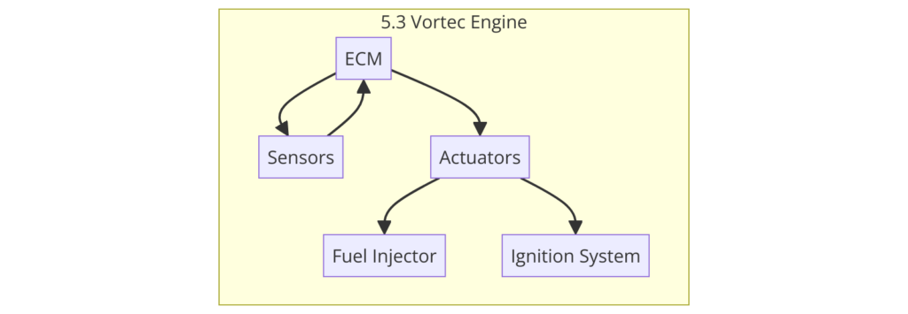
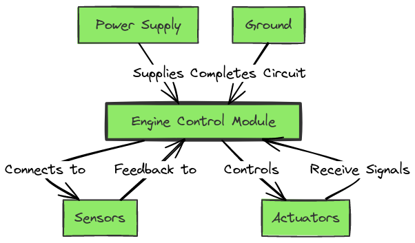
The 5.3 Vortec engine wiring harness diagram is a detailed schematic that illustrates the various electrical connections and components within the engine’s electrical system. Some of the key elements included in this diagram are:
- Engine Control Module (ECM)
- Fuel Injectors
- Ignition Coils
- Oxygen Sensors
- Crankshaft Position Sensor
- Camshaft Position Sensor
- Throttle Position Sensor
- Mass Air Flow Sensor
- Coolant Temperature Sensor
- Battery and Alternator Connections
5.3 Vortec Engine Wiring Harness Diagrams
Diagram 1:

Diagram 2:

Diagram 3:

How to Read the 5.3 Vortec Engine Wiring Harness Diagram
Reading and understanding the 5.3 Vortec engine wiring harness diagram can seem daunting at first, but with a little practice, it becomes a valuable tool in diagnosing and troubleshooting electrical issues. Here are some tips to help you navigate this schematic:
- Identify the Connector Locations: The diagram will clearly show the placement of various electrical connectors throughout the engine bay, making it easier to trace wiring and identify specific components.
- Follow the Color-Coded Wiring: Each wire in the diagram is color-coded, representing different circuits and functions. Pay close attention to these color codes to understand the flow of electrical signals.
- Trace the Connections: Carefully follow the wiring from one component to another, tracing the path of the electrical signals. This will help you identify potential issues, such as breaks or shorts in the wiring.
- Understand the Symbols: The diagram will use various symbols to represent different electrical components and connections. Familiarize yourself with these symbols to better interpret the information presented.
- Cross-Reference with the Vehicle’s Schematic: If available, compare the 5.3 Vortec engine wiring harness diagram with the overall vehicle schematic to gain a more comprehensive understanding of the electrical system.
Troubleshooting with the 5.3 Vortec Engine Wiring Harness Diagram
The 5.3 Vortec engine wiring harness diagram is an essential tool for troubleshooting electrical issues. By carefully analyzing the diagram, you can identify potential problems, such as:
- Wiring Breaks or Shorts: Trace the wiring to locate any breaks or shorts that may be causing electrical malfunctions.
- Sensor Failures: Use the diagram to identify the location and connections of various sensors, allowing you to diagnose and replace faulty components.
- Connector Issues: Inspect the electrical connectors shown in the diagram to ensure they are properly seated and free of corrosion or damage.
- Power and Ground Connections: Verify that the power and ground connections are secure and functioning correctly, as these are critical for the proper operation of the engine’s electrical system.
Conclusion
The 5.3 Vortec engine wiring harness diagram is a valuable resource for anyone working on or maintaining this popular engine. By understanding the components, connections, and troubleshooting techniques, you can effectively diagnose and resolve electrical issues, ensuring your 5.3 Vortec engine continues to perform at its best. Whether you’re a seasoned mechanic or a DIY enthusiast, mastering the wiring harness diagram is a crucial step in maintaining and repairing your vehicle.


