Understanding 7 Pin Wiring Diagram
Have you ever hooked up a trailer to your vehicle and found the lights or electric brakes not working properly? Trying to troubleshoot a trailer wiring issue can be incredibly frustrating…especially if you don’t have a reference for how the 7-way trailer plug and connections are supposed to be wired!
Trailer wiring diagrams are an incredibly handy resource when installing or testing a trailer wiring harness and 7-way connector. For some, reading complex wiring system diagrams is second nature. But for most of us understanding all the wires, colors and connections is challenging to say the least.
So what wires should be connected in a 7-way trailer plug to make the lights and brakes work properly? Read on for a helpful beginner’s guide to common 7-way trailer wiring setups.
What is a 7-Way Trailer Plug?
A 7-way plug is a large, round trailer connector that connects your trailer directly to the tow vehicle lighting system. It has become the most common style of trailer connector used today across most types of trailers including horse, cargo, RV and utility.
Earlier trailers used 4-way flat connectors limited to providing power for tail/brake lights and turn signals. As trailers became more sophisticated and started incorporating additional electrical functions like auxiliary power and electric brakes, the 7-pin connector emerged as the new standard.
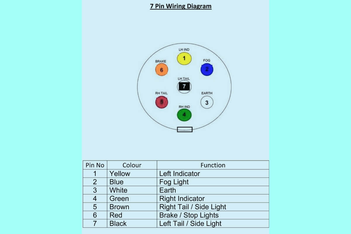
So why choose a 7-way plug versus a 4-way or 5-way? The 7-pin trailer wiring standard includes connections for:
- Left Turn/Stop Light (Brown)
- Right Turn/Stop Light (Green)
- Taillights (Red)
- Ground/- (White)
- Auxiliary Power/+ (Blue)
- Electric Brakes (Orange)
- Reverse Lights (Yellow)
With 7 conductors, it can handle all lighting as well as advanced functions for modern trailers. Although expandable to more pins if needed, the 7-way round design is also ideal from a usability perspective. The shape and larger pins allow for quick alignment and connection in any conditions.
For newer trucks and SUVs with complex vehicle wiring supporting towing, a 7-way socket is often standard from the factory. And many older vehicles can be upgraded to replace a 4-way socket with a 7-way using an affordable conversion kit.
So if your truck has a 7-way plug, chances are any single axle or multiple axle trailer you need to tow will also be outfitted with the 7-way connector.
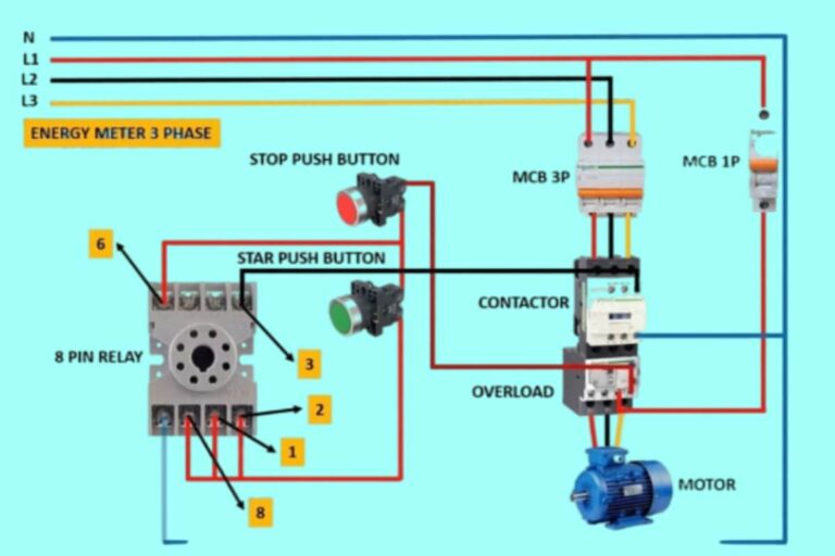
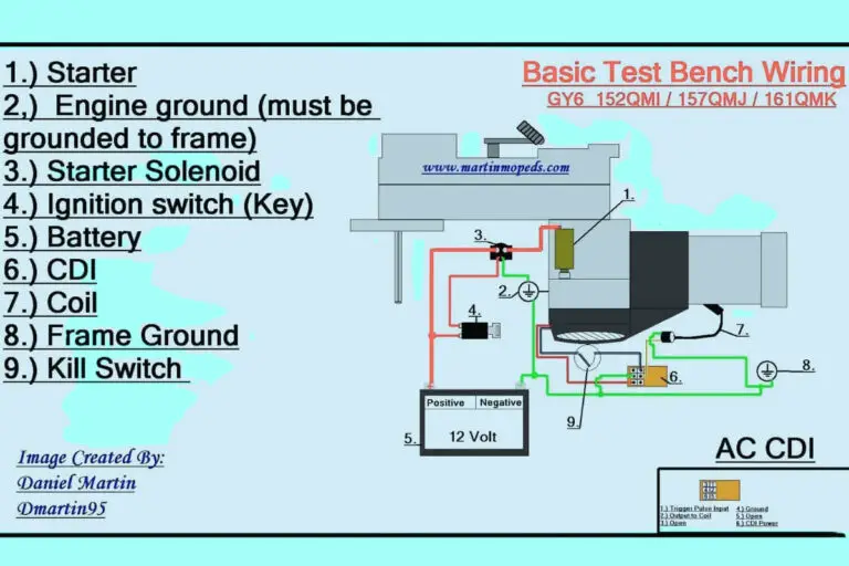
7 Pin Wiring Diagrams
Diagram 1:
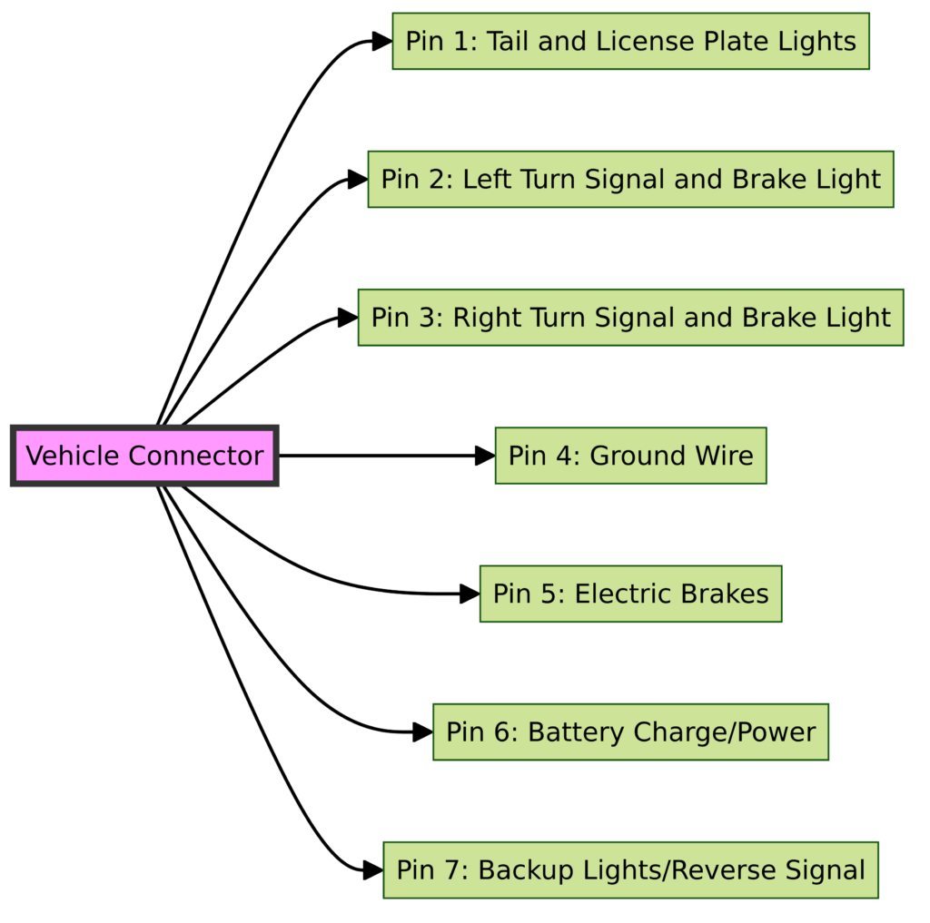
Diagram 2:
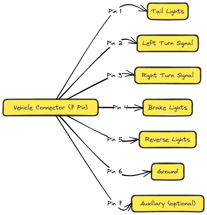
Diagram 3:
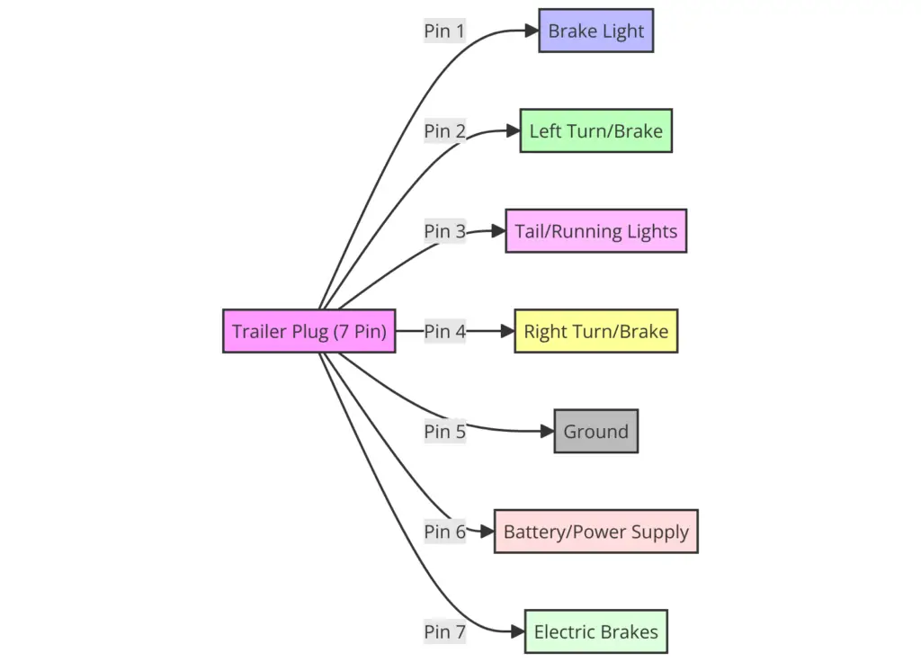
Diagram 4:
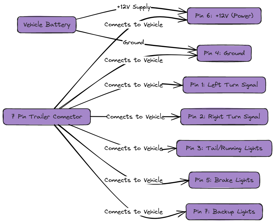
Diagram 5:

Common 7-Way Trailer Plug Wiring Colors and Functions
The specific purpose and wiring color code standards for a 7-way plug and connector are:
Brown Wire – Tail/Run/Turn/Brake Lights
The brown wire provides power for the tail, clearance, side marker, license plate and brake lights. This wire will connect to the tow vehicle’s left rear brake and turn signal circuit.
When the brakes are activated, the brown wire also engages the brake lights to notify vehicles behind you are stopping. And when signaling a right turn, it will cause the right rear trailer light to blink.
Green Wire – Right Turn/Brake Signal
The green wire performs similarly to brown but powers the separate right rear trailer turn/stop light. Hooking up to the tow vehicle’s right brake and turn signal system causes the right rear trailer lights to engage for stopping or signaling left turns.
Yellow Wire – Left Turn/Brake Signal
The yellow wire connects to the tow vehicle’s backup light circuit. This engages the trailer reverse lights to provide visibility behind your trailer at night when backing up.
White Wire – Ground
The white ground wire connects back to the tow vehicle body/frame providing a negative (-) reference voltage for the trailer lighting circuit. Proper electrical circuits require both positive (+) and negative potential to function.
Blue Wire – Auxiliary Power
The blue auxiliary wire (or battery charge wire) provides power to additional contacts on the trailer for charging the trailer battery, powering interiors lights, or energizing electric landing gear. It connects to the tow vehicle auxiliary power circuit found on many trucks.
Red Wire – Brake Lights
The red wire provides power to the standard brake light circuit at the rear of the trailer. Just like with the brown and green wires, this will cause the trailer brake lights to engage anytime the tow vehicle’s brake pedal is pushed.
Orange Wire – Electric Brakes
The orange connects to trailer electric brakes providing a power signal to actuate the trailer brake system whenever the tow vehicle brakes are applied. An additional box called a brake controller is often required in the tow vehicle to smoothly apply the trailer brakes.
7-Pin Trailer Wiring Diagram Basics
Now that you know the basic purpose and color coding of each wire in a 7-way plug, next we’ll cover some variations in how they are wired.
To ensure all lights and accessories function properly, you’ll need the correct wiring diagram specific to your trailer. The main connectors needing diagnosed are:
- The 7-way plug mounted on the vehicle (aka the tow vehicle side)
- The 7-way connector on the trailer (aka trailer side)
Let’s look at two common wiring setups – one for lighting and one for trailers with electric brakes.
Lighting Wiring
This simplified trailer wiring diagram applies to trailers that do not have brakes. Only the basic lighting functions are shown in this diagram.
As shown for lights-only wiring, you don’t need to connect or run all the wires:
- White ground wire must connect to tow vehicle frame
- Green and brown connect to tow vehicle brake/turn wiring
- Red brakelight power connects to tow vehicle brakelight circuit
- Blue auxiliary power connects only if needed
So for a basic trailer with just lights, you only need 4 of the pins wired – white ground plus wiring for stop/turn/tail. The blue auxiliary pin is optional and blacked out here.
Brake Wiring
For trailers with additional capabilities like electric or hydraulic surge brakes, both the brake light circuit and brake signal wire must be connected at the 7-way in addition to the lighting wires.
This diagram shows exactly how both the brake signal and light power should be wired to activate trailer brakes when the tow vehicle brakes are applied.
An electric brake controller installed in the towing vehicle modulates power to the trailer brakes proportionally based on deceleration of the tow vehicle.
The blue auxiliary pin is also connected here to provide charging power to the on-board trailer battery that drives self-contained electric trailer brake systems. This keeps trailer brake batteries maintained.
Now that you understand some basics around trailer lighting and brake circuits, let’s look at how to safely install or troubleshoot a 7-way plug.
How To Wire a 7-Way Trailer Plug?
While a seemingly simple device, correctly wiring a 7-way plug so that it works reliably requires some electrical skill and knowledge.
Improperly connected wires leading to burned out bulbs, damaged vehicle electronics, or even dangerous situations with trailer brakes not functioning are all possibilities.
Here is an overview of some best practices when wiring a 7-way trailer plug:
- Use a circuit tester to verify vehicle wire functions before tapping
- Select appropriate gauge trailer wiring
- Use crimping pliers and heat shrink for reliable pin connections
- Double check for crossed wires or loose connections
- Test directionals and brake activation before towing
It is highly advisable to enlist the help of an experienced auto electrician if you aren’t 100% confident in your wiring skills. Installed incorrectly, this seemingly basic plug can cause some serious headaches down the road.
Speaking of location, where do you typically find 7-way connectors? Next we’ll cover that.
Where are 7-Way Trailer Plugs Located?
Have you ever gone to hitch up your trailer and spent 10 minutes looking around the vehicle trying to find the trailer plug? Proper mounting location is another key factor in ease of use for your 7-way wiring system.
Ideally the 7-way wiring connector should be mounted just behind the hitch ball on your vehicle’s hitch system or bumper, like shown above. This keeps the 7-way trailer socket close to the trailer so the connection can be solidly made without a lot of slack in the line.
Run wiring cleanly under the vehicle along the frame so it is protected. Avoid running wires against sharp metal edges or near hot exhaust components.
Use silicone filled wiring looms to protect against mud, dirt and moisture. Leave several coiled wire turns once you reach the mount point to ensure slack when cornering or articulating the hitch.
For the trailer side, common 7-way plug mounting locations include:
- On the trailer tongue next to the hitch coupler
- At the front far side of enclosed trailers
- Under a removable cargo trailer bed near the hitch
Again allow plenty of wire slack but avoid loose hanging wires that can get damaged dragging the ground.
Troubleshooting 7-Way Trailer Wiring Issues
Inevitably with any electrical system complications can arise. So what symptoms or problems might you encounter with a 7-way trailer wiring setup? And how do you troubleshoot them? Let’s go over some common trailer electrical issues and resolutions.
- One or more lights not working? Check for damaged wires or loose plug pins. Exposed copper leads to shorts. Verify proper grounding.
- Lights flicker / dim? Be sure the trailer battery is fully charged. Check for shorts lighting circuit resistance leading to voltage drops.
- Brakes not engaging properly? Electric brake controllers can fall out of sync. Confirm trailer brake wiring is correct.
- No trailer power or lights? Start by testing operation plug pins with circuit tester. Then trace individual circuits checking for connectivity breaks.
Be sure to inspect wiring for cuts, fraying or corrosion. Worn insulation leads to shorts especially in damp conditions. Reflow any questionable solder joints and protect with heat shrink or dielectric grease.
LED lights often create issues. The sensitive electronics in LEDs can react poorly to voltage spikes. Install capacitors or filters to smooth voltage.
And don’t forget to check grounds. Trailers can vibrate causing screws and bolts to loosen from the frame over time.
Still finding an electrical gremlin you can’t resolve yourself? Every part of the trailer wiring system needs to operate properly for the lights and brakes to activate as expected. Hire an experienced trailer wiring troubleshooter.
Next we’ll cover specifically how to test a 7-way trailer connection.
Testing a 7-Way Trailer Wiring Plug
Working with a partner, visually inspecting wires, and methodically testing circuits is key for diagnosing trailer wiring problems.
Here is a quick step-by-step process for testing a 7-way plug:
- Inspect wires and connectors for damage before testing
- Have helper cycle through functions – lights, signals, brakes – while you observe trailer
- Check that running lights, turn signals, brakes engage properly
- For electric brakes use a multimeter to test signal wire voltage (~12V)
- Use a circuit tester to confirm connectivity pin-by-pin on both plugs
- Perform resistance check ensuring < 2 Ohms across wires
Methodically verifying the electrical signals at both the vehicle and trailer side of the 7-way wiring helps isolate connectivity issues.
Pay special attention to the white ground and orange electric brake wire circuits when trailer brakes are not activating properly. Tracing and testing the exact pinouts matches vehicle output to trailer input.
And remember to be safe when testing! Always properly support the trailer’s tongue weight, chalk tires in place, and never stand directly behind when confirming brake light signals.
Review the next section to explore some frequently asked questions about 7-way trailer wiring installations.
Frequently Asked Questions about 7-Way Trailer Wiring
Do all trailers use 7-way plugs?
No, some older or custom trailers still rely on 4/5-way flat connectors. But 7-way round has become the new standard across most trailer types.
Where does the 7-way trailer plug connect to on my truck?
Most modern trucks and SUVs come equipped with a 7-way socket ready to accept the trailer plug. Look under the rear bumper or builtin hitch receiver.
What are the black and purple wires sometimes included?
The black and purple wires are optional set as auxiliary power #2 and #3 for extra functions. Trailers with additional voltage needs sometimes require the spare power.
My trailer lights work but brakes don’t – why?
If lights come on but trailer brakes don’t engage, the brake signal wire is not wired correctly. Double check your 7-way pinout for the orange brake power wire.
Do I need a special brake controller to use electric trailer brakes?
Yes. The electric brake wire provides a modulated voltage signal to trailer brakes. An aftermarket brake controller installed under the dash modulates power based on braking intensity.
Why do my new LED lights flash oddly?
LED electrical noise can trick brake light controllers resulting in odd flashing. Electrical filtering is recommended for using LED lights.
Everything was just working then lights went out – now what?
Start by checking under trailer frame and hitch ball for any wires pulled loose from twisting or turning. Then systematically check each light, wire junction and plug.
Hopefully reviewing trailer wiring diagrams along with outlines for proper installation, testing and troubleshooting helps provide more confidence in resolving 7-way trailer issues. Let’s recap a few key tips.
Conclusion and Summary
Hooking up trailer lighting and brakes via that small 7-pin connector tucked under your vehicle bumper may seem daunting. However, by following wiring diagrams, methodically testing connections, and properly troubleshooting issues, getting your trailer fully functioning is very achievable.
To recap key aspects for 7-way trailer wiring:
- Use diagrams specific to your trailer setup – Don’t just rely on generic 7-way pinouts. Know how each wire should be connected for your unique trailer’s lighting and electric brake needs.
- Inspect wires, grounds and connections – Corrosion plus vibration can loosen even the best installed systems over time. Check that everything is clean, intact and tightly fastened.
- Confirm proper electrical signals at the plug – Use a circuit tester to validate connectivity pin-by-pin before assuming issues are wiring related. Detect shorts right at the connector.
- Trace and test every wire, junction and light – Do not assume partial functionality means an intermediate junction is properly connected. Methodically verify end-toend function of each circuit powered via the 7-way plug.
We hope reviewing common 7-way trailer wiring diagrams, install tips, testing procedures and troubleshooting tricks gives you more confidence working with 7-way systems. Properly installing and maintaining your trailer wiring translates directly into towing safety and peace of mind.
Now before heading out on the road, be sure to also check your hitch setup, safety chains, brake fluid and tire pressure. Regular maintenance and inspection ensures the most enjoyable trouble-free trailering and towing experiences.
Let us know if we can help explain any other aspects of truck and trailer maintenance, operation and repair!

