7 Way Trailer Wiring Diagram
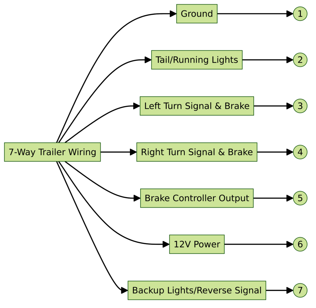
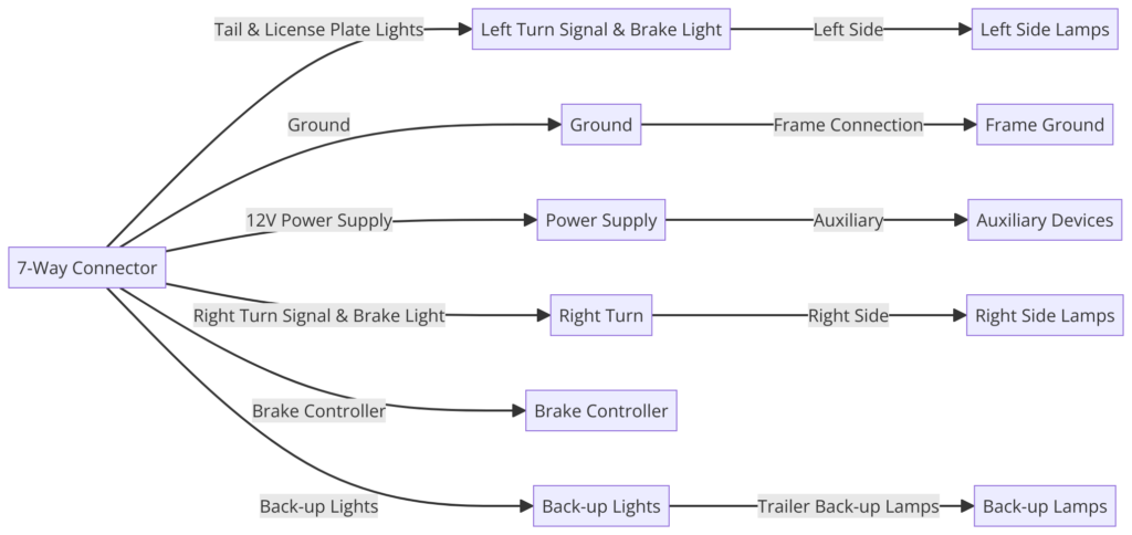
A 7-way trailer wiring diagram is a schematic that shows the pinout and function of each wire in a 7-pin connector. Most modern trailers use a standard 7-pin connector that contains one wire for each tail light, turn signal, brake light, and electric trailer brake. An additional pin provides 12V power for accessories.
The diagram uses color coding and labeling to identify each circuit at a glance. This makes it easy for installers to match up the wires without needing advanced electrical knowledge.
7 Way Trailer Wiring Diagrams
Diagram 1:

Diagram 2:

Diagram 3:

Diagram 4:

Purpose of a Wiring Diagram
Wiring diagrams serve an important purpose for installing trailer lighting. Since trailers connect to the tow vehicle’s electrical system, it’s essential that the correct wires pair up on both sides. Mixing up wires can lead to shorts, blowing fuses, and lights not functioning.
By following a 7-way trailer wiring diagram, you can be certain that the trailer lights will work as intended. The diagram shows where each wire goes both on the vehicle and trailer side.
Components of a 7-Way Diagram
A 7-way trailer plug contains the following wires and circuits:
Power Wires
- Ground – Provides a common ground for all circuits. Typically white wire.
- Positive Power – 12 volt hot lead to power trailer accessories. Typically red wire.
Turn Signals and Brake Lights
- Left Turn/Stop – Powers left turn signals and brake lights. Typically yellow wire.
- Right Turn/Stop – Powers right turn signals and brake lights. Typically green wire.
Accessory Power
- Auxiliary Power – Extra 12V power for additional accessories. Typically blue wire.
- Back up Lights – Engages back up lights when vehicle shifter is moved to reverse. Typically black wire.
- 12V Battery Charge – Allows trailer battery to charge when connected. Typically brown wire.
How to Read the Diagram
7-way trailer wiring diagrams read from top to bottom for the vehicle side, and bottom to top for the trailer side.
Trailer Side vs Vehicle Side
The trailer side of the diagram starts at the base of the page, showing the view looking inside the 7-way connector. The vehicle side shows the view looking into the vehicle’s 7-way plug near the hitch.
This allows you to pinpoint exactly which vehicle wire should mate up with each corresponding wire on the trailer plug.
Wire Colors and Functions
The color of each wire is standardized for all trailer wiring. For example, yellow always carries the left turn/brake light circuit. This color coding helps avoid mixing up wires that carry different circuits.
Some diagrams may use abbreviations or alternative names for each function. For example LT may stand for left turn instead of the full wording. But in all cases the wire color remains the same.
Using the Diagram to Connect Lights
The main purpose of a 7-way diagram is to ensure proper mating of all wires between the trailer and vehicle. Here is a typical sequence when connecting lights:
- Run wires from trailer light assemblies to 7-way plug mounting location
- Install 7-way plug and connect all wires per diagram colors
- Ground white wire to trailer chassis
- Locate vehicle’s 7-way socket near hitch and plug in trailer connectors
- Test all light functions using vehicle headlight and brake pedals
If certain lights do not function, double check that wire colors align properly on both the vehicle and trailer sides using the wiring diagram.
Common Mistakes to Avoid
These wiring mistakes can be avoided by properly using the diagram:
- Switching left and right turn signal wires. Trailer flashers will blink opposite sides.
- Brake lights not working: often a ground wire issue
- Connecting blue accessory wire to positive trailer feed – should only energize from vehicle
- Overloading accessory circuit by using too small of a wire gauge
Always double check for pinched wires, fraying, corrosion, or loose connections that impair electrical continuity. Use dielectric grease to seal plugs and prevent corrosion or moisture penetration.
Final Thoughts
Having basic knowledge of how to read a 7-way wiring diagram enables safe and reliable trailer light function. Consult the diagram any time you connect a different trailer, repair or replace wires, or are troubleshooting electrical issues. Consistently verifying that wires match on both trailer and tow vehicle goes a long way for success!
