Demystifying 8 Pin Relay Wiring Diagrams
Have you ever opened up a relay and seen an array of pins and wondered – how do I figure out how to wire this thing?
Relays may seem confusing, but have no fear – this guide will provide everything you need to understand 8 pin relay wiring diagrams!
We’ll cover topics like:
- What is a relay and how do relays work
- The purpose and function of each pin in an 8 pin relay
- How to interpret 8 pin relay wiring diagrams
- Wiring 8 pin relays for various applications
- Relay circuit design tips and examples
And much more!
So if you want to become a master at wiring 8 pin relays, read on!
What is a Relay?
Before we jump into the specifics of 8 pin relays, let’s make sure we understand what exactly a relay is and how it works.
A relay is an electrically operated switch that uses an electromagnet to move the switch contacts and control a load circuit.
Relays allow a lower power circuit to switch a higher power circuit on and off while keeping them isolated.
The relay has two separate circuits:
- A control circuit which carries a relatively small electric current to energize the electromagnet
- A load circuit which carries a much larger electric current to the load being switched on and off
The electromagnet in the relay creates a magnetic field when the control circuit is energized. This pulls the armature towards it and the attached contacts switch from their normally open position to closed.
The movement of the contacts controls the flow of electricity in the load circuit to turn something on or off.
Why Use a Relay?
Relays have some key advantages that make them useful:
- They provide electrical isolation between control and load circuits
- They allow a low power circuit to control higher voltages/currents safely
- They can switch many contacts at once
- They provide reliable switching for a variety of applications
Some example uses for relays include:
- Turning motors on/off
- Running timer circuits or latching relays
- Switching large current devices like heaters or lights
Now let’s break down the specifics of 8 pin relays!
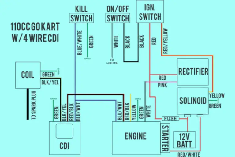
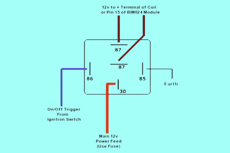
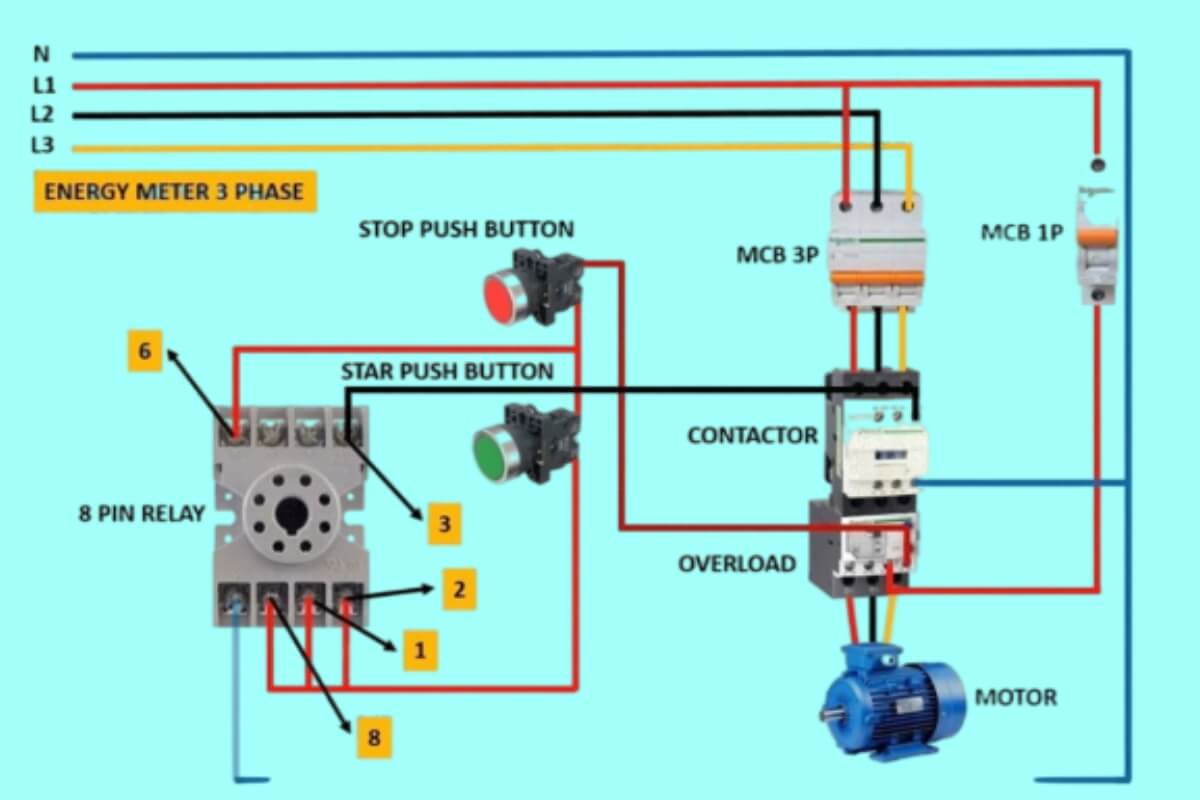
8 Pin Relay Wiring Diagrams
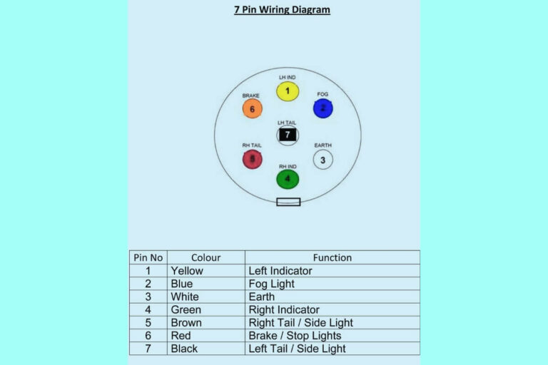
Diagram 1:
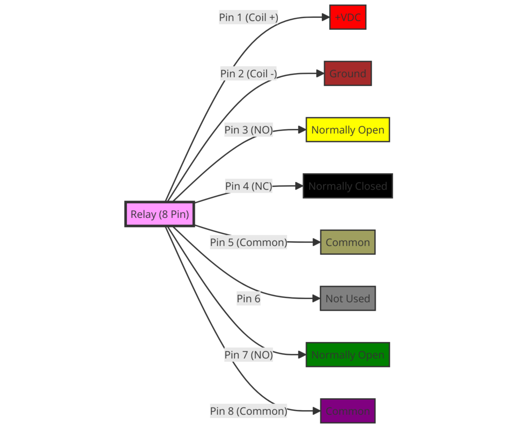
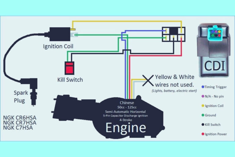
Diagram 2:
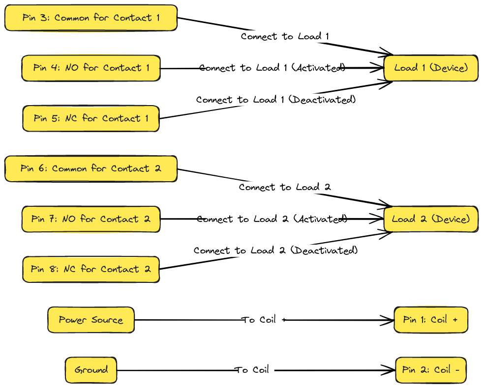
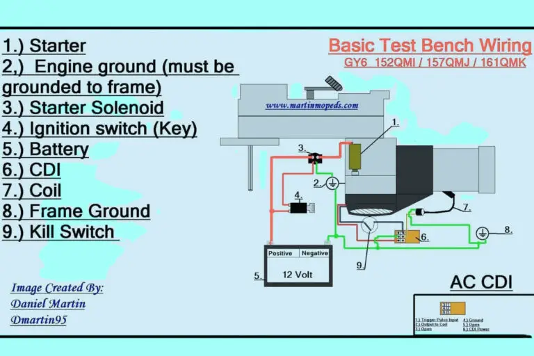
Diagram 3:
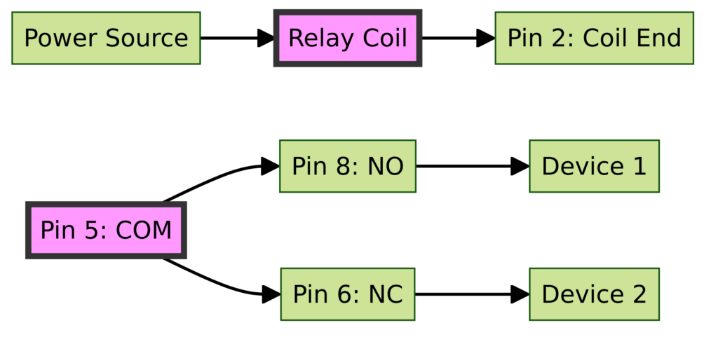
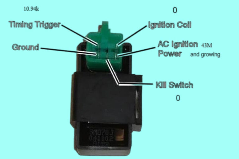
Diagram 4:
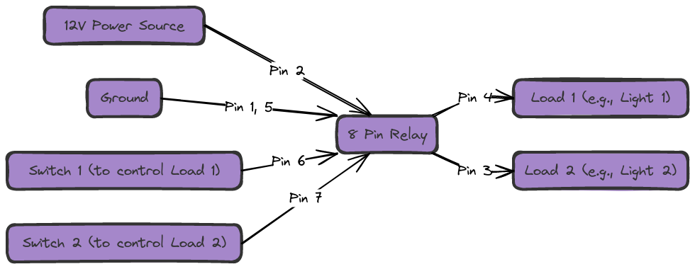
Components of an 8 Pin Relay
An 8 pin relay contains these key components:
- Coil: Provides the electromagnet function to move the switch contacts. Carries control circuit current.
- Contact: The output switch contacts controlled by the magnetic coil. Switch opens/closes load circuit.
- Normally Open (NO) contact: Contact is open when the coil is not energized. Closes when activated.
- Normally Closed (NC) contact: Contact is closed when coil not energized. Opens when activated.
- Common (COM) contact: Shared point both NO and NC contacts connect to.
- Pin connections: Provides electrical connections to contacts and coil
Now let’s explore what each pin on an 8 pin relay does.
8 Pin Relay Terminal Functions
Here is an overview of the purpose of each pin:
Pin 1 – Input power supply positive to the coil
Pin 2 – Input power supply negative to the coil
These two pins operate the relay’s electromagnet coil
Pin 3 – Common (COM) contact
Pin 4 – Normally Closed (NC) contact
Pin 5 – Normally Open (NO) contact
These three pins are the output switch contacts
Pin 6 – Not connected (may be omitted)
Pin 7 – Not connected Pin 8 – Not connected
Pins 6-8 are unused
So in summary, pins 1-2 operate the electromagnet coil while pins 3-5 are the relay output contacts.
8 Pin Relay Coil Pinouts
As covered above, pin 1 connects to the positive side of the coil power supply, while pin 2 connects to negative.
The coil pins provide power to operate the electromagnet which changes the position of the output contact.
For an 8 pin relay usually a 5V, 9V or 12V power source is used to provide power to the coil through pins 1 and 2.
The coil voltage rating and input power specifications differ between relay models, so be sure to check your specific relay when determining what power supply to use.
Proper coil pin voltage is critical to ensure reliable operation of the relay.
Wiring an 8 Pin Relay as a Latching Relay
One very useful way to wire an 8 pin relay is in latching mode.
This allows the relay to function as a flip-flop switch, meaning it will alternate between on and off states each time it is triggered.
To achieve this, pins 1 and 2 are powered constantly to hold the state of the coil.
A normally open momentary push button connects pin 1 to ground. This forms a circuit to energize the coil and change the state of the output each time pressed.
A diode is connected across the coil (pins 1 & 2) to provide a path for the reverse EMF spark when the coil is disconnected, protecting the transistor controlling the ground.
Latching relays are useful for applications like controlling lights, motors, or other loads you want to turn on/off with a single momentary switch.
Now let’s look at controlling higher power loads.
Using 8 Pin Relays for Switching Higher Loads
A major benefit of relays is how they isolate control and load circuits while allowing lower power circuitry to control higher voltages and currents.
This allows safe, reliable control of devices like motors, heaters, or lights that draw substantial amperage.
For example, this relay circuit uses a 5V microcontroller to control a 120V AC motor.
The microcontroller activates the 5V relay coil through transistors, closing the 120V contacts to start/stop the motor.
The optoisolators provide feedback on motor operation to the controller while maintaining over 2000V electrical isolation.
While the relay’s switch contacts are rated for 10A+ at 120V in this circuit, the microcontroller uses less than 150mA at 5V.
This demonstrates how smaller controllers can activate high power loads while remaining isolated and protected.
Now let’s look at some full 8 pin relay wiring examples.
8 Pin Relay Wiring Diagram Examples
Reviewing some example wiring diagrams will help solidify understanding of real-world 8 pin relay implementations.
Here are two common examples:
SPDT DC Relay
This shows an 8 pin Single Pole, Double Throw (SPDT) DC relay controlling a DC load like a motor or lamp.
Pin 1 & 2 receive DC power for the coil. Pins 3, 4, & 5 connect to the load with pin 5 closed when activated. Notice pin 4 provides an NC function if needed.
DPDT AC Relay
Next is a Double Pole, Double Throw (DPDT) AC relay for switching an AC load.
It functions the same but with 2 common lines allowing 2 isolated NO contacts to close when activated. Great for switching multi-wire AC circuits to a load.
As you can see, once you understand the purpose of each pin, reading a wiring diagram becomes straight-forward!
Now let’s explore some typical 8 pin relay control applications.
Typical Applications of 8 Pin Relays
Some of the most common uses for 8 pin DC or AC relays include:
Controlling Electric Motors
As covered previously, using relays to start, stop, reverse, or protect motors is very common – especially at higher voltages.
Running Timer Circuits
Wiring relays in latching modes allows simple timer circuits to function for intermittent load control.
Automotive Uses
Relays operate a wide variety of automotive functions like headlights, starter motors, pumps, and more due to their durability and electrical isolation.
Industrial Control Systems
Relay racks mount groups of relays to automate processes in factories or distribution systems.
Home/Building Automation
From switching lamps to operating automatic blinds to irrigation control, relays toggle plenty of residential functions.
These are just a few examples – 8 pin relays have tremendously versatile applications.
Now for some key wiring best practices…
Tips for Properly Wiring 8 Pin Relays
Follow these guidelines when working with relays for successful, safe operation:
- Verify your relay coil voltage rating before applying power
- Use flyback diodes for DC coils to prevent voltage spikes
- For AC coils, connect a capacitor to increase power factor
- Wire with sufficiently sized loads wires for the rated amperage
- Use proper overcurrent and surge protection devices
- Provide adequate relay socket clearances to prevent shorts
Proper control and load circuit separation is also critical for protection and performance.
With good practices, 8 pin relays will deliver reliable automated switching.
Finally, let’s answer some common questions.
Frequently Asked Questions About 8 Pin Relays
Can I use a 5V Arduino to control a 120VAC 8 pin relay?
Yes, as long as you properly isolate the coils from contacts and drive the relay with a transistor.
What gauge wire should I use for the contacts?
Select wire gauge based on rated max switch amps. For 10-15A loads, use 14 gauge or thicker wire.
Do all 8 pin relay contact terminals function the same way?
No, while that is a common configuration it can vary. Always check your specific relay diagram.
How do I determine the coil power needed?
Check markings on the relay for nominal coil voltage and power draw ratings.
Hopefully those answers some additional questions about proper 8 pin relay usage!
Conclusion
In closing, while 8 pin relays may seem mystifying at first, once you understand their internal components and pin layouts reading schematics and wiring them becomes straightforward.
We covered relay basics, 8 pin terminal functions, coil pinouts, wiring examples, applications, and best practices.
So now you’re equipped to read 8 pin relay diagrams, implement them properly in your own projects, and take advantage of these versatile electromechanical workhorses!
If you have any other relay or relay circuit questions, ask below in the comments section!

