Ford Alternator Wiring Diagram Internal Regulator
Have you ever opened the hood of your Ford and stared blankly at the jumble of wires connected to the alternator? Does the task of wiring an alternator seem confusing and complicated? If so, this blog post is for you!
Wiring a Ford alternator with an internal regulator can be simple if you understand the key connections and how to hook everything up properly. We’ll walk through the entire process step-by-step.
We’ll cover topics like:
- What is an alternator and how does it work?
- Alternator designs – internally vs externally regulated
- Diagramming the basic Ford alternator connections
- Step-by-step wiring instructions
- Troubleshooting tips
- Additional wiring diagrams by Ford model
After reading, you’ll have the knowledge to take on Ford alternator wiring with confidence!
What Is an Alternator and How Does It Work?
Before jumping into the specific Ford alternator wiring setup, it helps to understand exactly what an alternator is and how it works.
An alternator is the modern solution for powering your vehicle’s electrical system, having replaced the older generator design years ago. The key difference is that an alternator powers the vehicle while it’s running, whereas a generator relied on battery power to initially get the engine cranked and started.
Here’s a quick overview of how an alternator functions:
- Converts mechanical rotation into electrical energy using magnets and wire coils
- Regulates itself using an internal voltage regulator
- Charges the battery
- Powers all electronics when engine is running
Without a properly working alternator, your battery would quickly drain and the vehicle would shut off. So making sure it’s wired correctly is crucial!
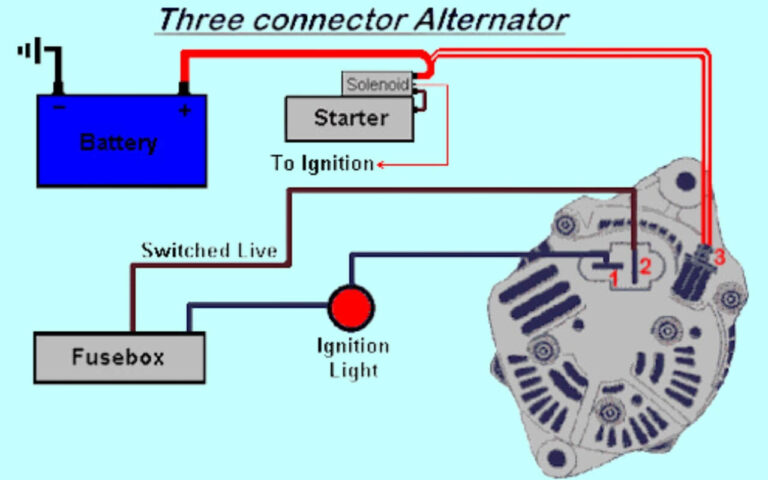
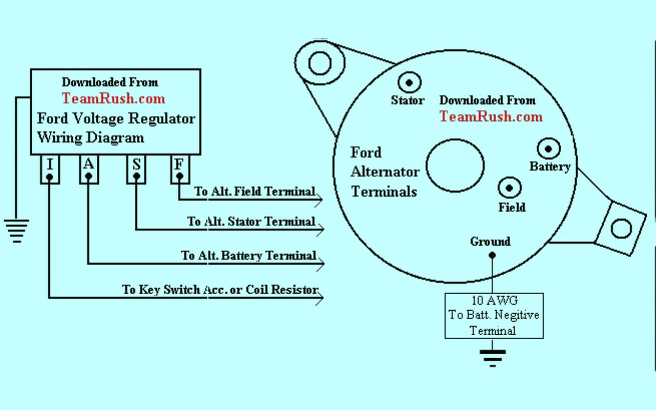
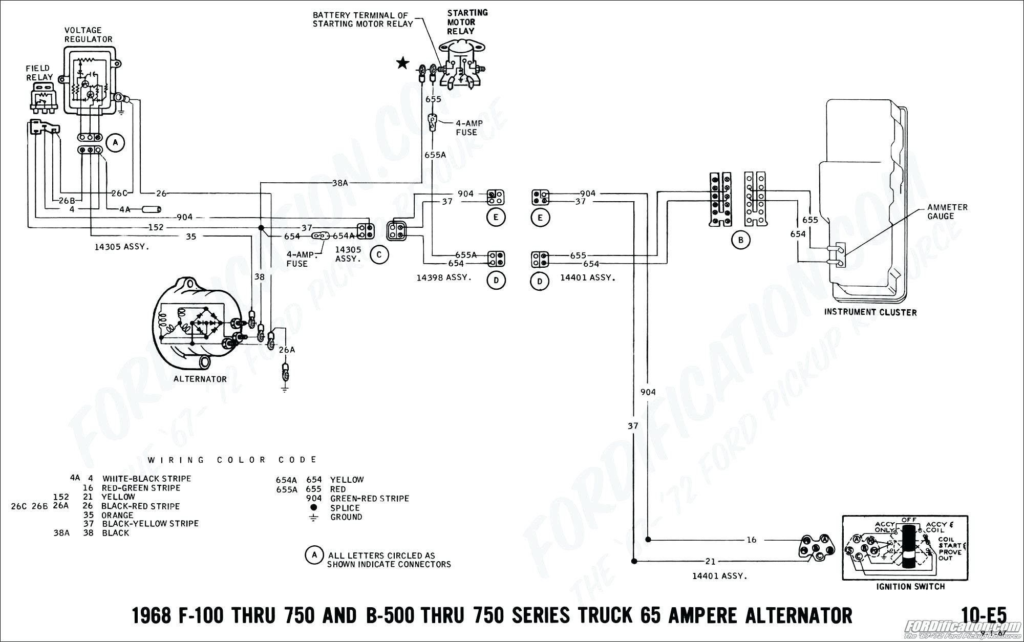
Ford Alternator Internal Regulator Wiring Diagram
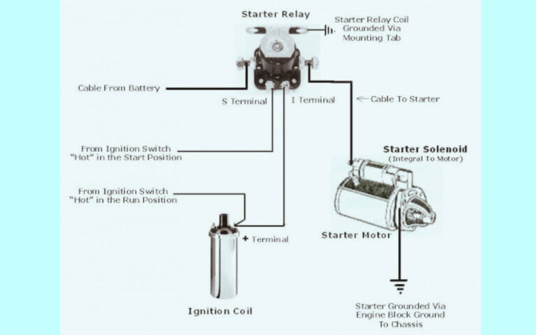
Diagram 1:
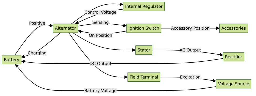
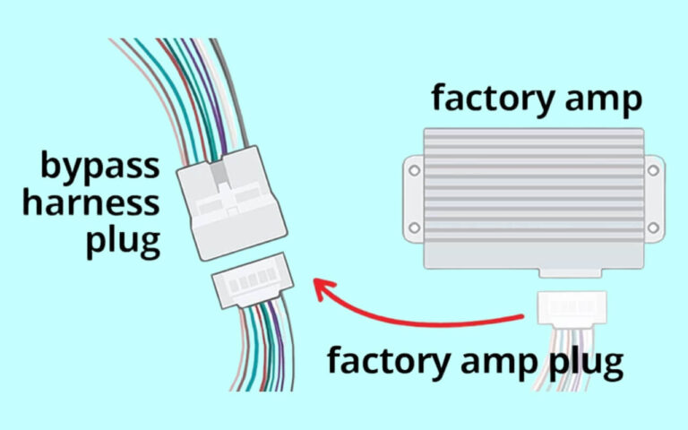
Diagram 2:
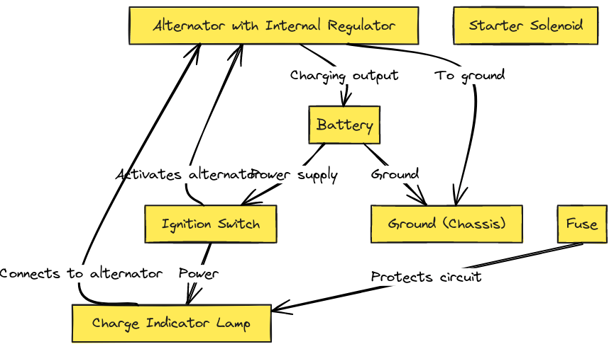
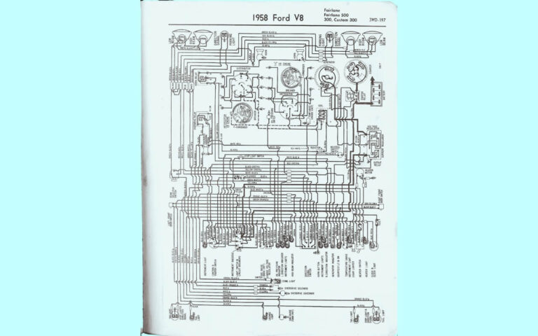
Diagram 3:

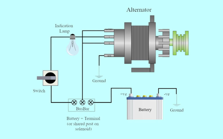
Diagram 4:

Alternator Designs: Internally vs Externally Regulated
Early alternators used an external voltage regulator, which was a separate unit wired into the circuit. This device monitored electrical loads and adjusted alternator output to maintain a steady system voltage.
However, modern alternators have a built-in regulator that performs the same task. These are known as internally regulated alternators.
There are several key advantages to the internally regulated design:
- Simpler wiring
- Fewer connections to fail
- Regulator senses alternator conditions directly
- Compatible across more vehicle makes and models
Both types remain in use today. But the internal regulator style has largely taken over and is the easiest to wire up from scratch. Ford factory alternators use this preferred setup, which is why we’ll focus on it in this tutorial.
What You Need to Wire a Ford Alternator
With the background covered, let’s talk about actually wiring a Ford alternator with internal regulator. Here’s what you’ll need:
Parts:
- Alternator (new or rebuilt)
- Wires
- Connectors
- Fuses or circuit breaker (recommended)
Tools:
- Wrench set
- Wire crimper
- Volt meter (helpful)
Vehicle Information:
- Basic electrical understanding
- Service manual (recommended)
Also, inspect your existing setup if available. That gives helpful context and you may be able to reuse some wires or connections.
With those basics covered, let’s look at the typical Ford alternator wiring connections.
Diagramming the Basic Ford Alternator Connections
Here is a simple diagram showing the most common Ford alternator wiring setup:
As you can see, there are only a few key connections:
- Charge wire to battery (supplies charging current)
- Ignition wire to ignition switch (turns alternator on/off)
- Voltage regulator wire to warning lamp (alerts of issues)
- Ground wire (completes circuit for current flow)
Next let’s look at each connection’s purpose and options for hooking things up.
Alternator Charge Wire
The main charge wire sends current to the battery to replenish and maintain its charge. This is the thickest wire in the whole setup.
For optimal performance, a 6 or 8 AWG wire is recommended for the alternator charge connection. Ensure it’s securely terminated.
The other end connects to the positive post on the battery or the battery stud located on the starter solenoid. Either works fine.
Installing a fused link or circuit breaker safeguards from shorts. Size around 100-110% of the alternator amp rating for ideal protection.
Ignition Wire to Switch
This wire turns the alternator off and on based on ignition switch position.
When ignition is turned to the “Run” position, 12-volt power flows through to the voltage regulator telling it to start charging.
Some choose to wire the ignition circuit directly. But it’s cleaner and easier to simply use the supplied pigtail off the alternator.
Either way takes only a 14 or 16 AWG wire to handle the compact current draw.
Voltage Regulator/Warning Light Wire
As mentioned earlier, modern alternators self-regulate voltage internally.
Still, this wire connection is useful for two reasons:
- Powers warning light on dash
- Backup tap into voltage regulation system
The warning light alerts if either battery charge or alternator output voltage drops too low. This alerts the driver of an issue.
However, even with bulb burnt out the alternator maintains control internally through the voltage regulator connection. So the system is not dependent on the warning lamp working properly.
To connect this sense circuit, run a 14 or 16 AWG wire to the warning light or directly to ignition switch. If light is inop just cap off wire instead.
Ground Wire
Proper grounding finishes off the basic Ford alternator wiring setup.
Using aground strap, connect directly to the alternator mounting bracket and vehicle frame or negative battery terminal.
Don’t neglect the ground circuit or the chargesystem cannot operate correctly!
Step-by-Step Wiring Instructions
Now that we’ve covered the purpose of each connection, let’s look at the actual step-by-step process to get your Ford wired up properly.
1. Gather Wires and Connectors
Collect the following based on your specific project:
- Wires (4 AWG charge wire plus misc lengths)
- Eyelet connectors
- Insulated spade terminals
- Heat shrink
Tip: Label wires using tape for easy identification.
2. Mount Alternator
Bolt or brace the alternator firmly to the engine. Check any existing mounts for issues which could cause misalignment.
3. Connect Battery Wire
Attach your 4 AWG charge wire to the B+ terminal on the rear of the alternator using an eyelet connector.
Run the wire to the battery, fuse block, or starter solenoid and terminate securely.
Install fuse link if desired.
4. Connect Ignition Wire
Next comes the ignition trigger wire.
Aim for 12 volts controlled by ignition switch. Tap into an existing switched circuit or use the factory 4-pin plug if reusing pigtail.
With aftermarket alternator, simply connect ignition activation lead.
5. Attach Voltage Regulator Wire
Now hook up the voltage regulator reporting circuit.
Plug pigtail connector to matching plug on wiring harness if reusing factory terminals.
If adding new wiring, crimp on an insulated spade terminal to tap into warning light circuit.
Or splice into wire that’s livewhen ignition is in “RUN” position.
6. Ground Alternator
Finally, complete the circuit with a solid body or frame ground.
Use heavy gauge wire, ground strap, or mounting bolt.
Without proper grounding your charging systemwon’t work!
Double check connections then startup vehicle. The battery warning indicator on dash should go out once engine starts.
Use a voltmeter to verify charging voltage at battery terminals. Check owner’s manual for specifications if unsure. You can also ensure the alternator is charging by carefully feeling case temperature rise after a short drive.
And that wraps up the basics of Ford alternator wiring using the simple internally regulated design!
Troubleshooting Tips
Most charging issues can be pinpointed to either wiring faults or a bad alternator.
Here is a quick checklist if facing problems:
- Inspect and remake loose connections
- Check voltage at alternator large output terminal (~13-14.5 volts expected)
- Verify ground connection resistance low
- Listen for bearing noises or grinding sounds
- Test alternator output or take to parts store for testing
Also note that a failing battery can cause charging problems. Have battery load tested at an auto parts retailer if concerned.
With the above process, you should be able to quickly diagnose and fix common Ford alternator wiring problems.
Frequently Asked Questions
Here are answers to some common questions about wiring a Ford internal regulator alternator:
What’s the typical alternator voltage output?
Most Ford models target 13.5 to 14.5 volts when engine is running. Check service manual for exact charging specification.
Can I upgrade to a higher amp alternator?
Yes, just make sure wiring, fuses, and brackets are rated to handle increased output. Ford vehicles can usually handle upgrades to 60-200 amps max.
Why does my battery light stay on with new alternator?
Ensure all wiring connections are clean and secure. Also check the warning lamp bulb – if burnt out the light will stay on constantly. Changing the bulb or disabling the warning circuit typically resolves this nuisance light issue.
How do I convert an old external regulator to internal?
Use a “3-wire” late-model Ford alternator. Run Charge, Ignition, and Warning Light wires per diagram above. Cap or remove voltage sense wire from old regulator harness. Add diode trio on exciter wire if 3G upgrade.
Additional Diagrams
Here are some other common Ford alternator wiring implementations:
Ford 2G Series Alternator Wiring
Older dual connector design with external regulator. Common on 1960s and 1970s Ford models.
Ford 3G Series Alternator Wiring
Introduced in 1994 with single connector case. Has three terminals. External regulator until 3G-ALT variant with internal regulator and diode trio.
Ford ECO Variable Voltage Alternator
Newer design that adjusts output based on electrical load to improve fuel efficiency. Found on many modern Ford trucks and SUVs:
As shown by the various diagrams, while the connection points may differ slightly, the functionality remains generally the same. Use the above troubleshooting tips to quickly diagnose any wiring issues.
Conclusion – Key Takeaways for Wiring a Ford Alternator
And there you have it – a complete step-by-step guide to Ford alternator wiring.
The good news is that thanks to the internal voltage regulator design, wiring a Ford alternator is actually quite simple compared to external regulator setups.
Here are the key takeaways:
- Most Ford alternators use an internal regulator for easy wiring
- Main Charge wire handles heavy current flow to battery
- Ignition wire turns alternator on/off
- Warning light circuit monitors voltage and alerts of issues
- Solid ground connection is vital
- Troubleshoot wiring issues before assuming bad alternator
We also discussed different connector styles and diagrammed a few classic Ford alternator wiring implementations as references.
I hope you found this help in understanding how to wire a Ford alternator. The next time you peer under the hood at the intimidating mess of wires, you’ll know exactly what to do thanks to this alternator wiring guide!
Now kick back and enjoy turning the key and having your battery charged reliably and consistently thanks to solid Ford alternator wiring. You got this!

