Finding Exact 1979 Ford F150 Instrument Cluster Wiring Diagram
So you’ve got a classic 1979 Ford F150 truck and need the proper wiring diagram for the instrument cluster – we’ve been there! Tracking down the exact schematic for your truck’s year, make and model can be frustrating when all you want to do is get your project finished.
This blog post answers:
What is the easiest way to find and read the correct instrument cluster wiring diagram for your 1979 F150?
The best approach is to access online Ford truck forums and resources that provide diagrams for free, learn to interpret them properly, and leverage the color coding and connector info for each component. We’ll walk through specific sections below.
We’ll discuss topics like:
- Where to access free 1979 F150 wiring diagrams online
- Understanding the different diagrams for instrument clusters
- How to read wire colors, gauge connectors, etc
- Connecting your ignition switch, indicator lights and engine sensors
- Finding diagrams for F150 models with specific features
- Using your diagram to install a new instrument cluster or troubleshoot issues
- Expert tips from mechanics familiar with these trucks
So if you need to connect or troubleshoot your 1979 Ford F150 instrument cluster, or are installing aftermarket gauges, this post has you covered! Let’s get started.
Introduction – Why You Need the Correct 1979 F150 Wiring Diagram
When working on your classic Ford F150 truck, having an accurate and up-to-date wiring diagram is critical for tracing electrical connections and diagnosing issues.
For the instrument cluster in particular, the correct diagram helps ensure all your dashboard lights, gauges and engine sensors connect properly to power, ground and computer/controller components under the hood.
Without it, trying to wire a new cluster or just connect accessories like trailer lights can be incredibly frustrating. And could even lead to electrical fires or other dangerous issues from wires shorting out.
So before you dig into any electrical work on your 1979 Ford truck, it’s important to get the manufacturer schematic relevant to your specific model. In this post we’ll cover exactly how to do that online, as well as key things to look for as you read and interpret the diagram.
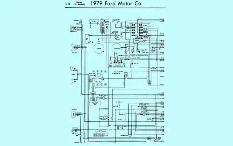
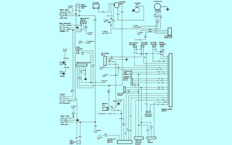
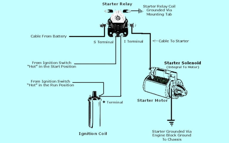
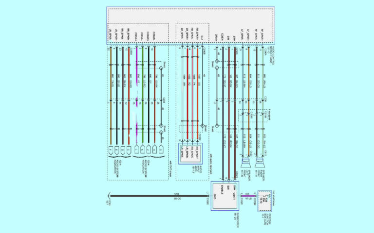
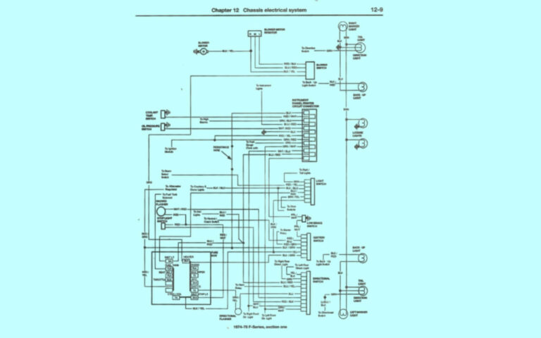
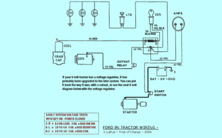
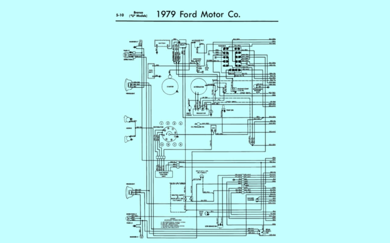
1979 Ford F150 Instrument Cluster Wiring Diagrams
Diagram 1:
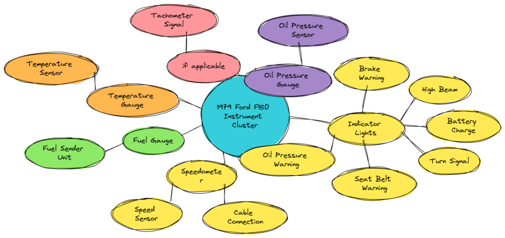
Diagram 2:
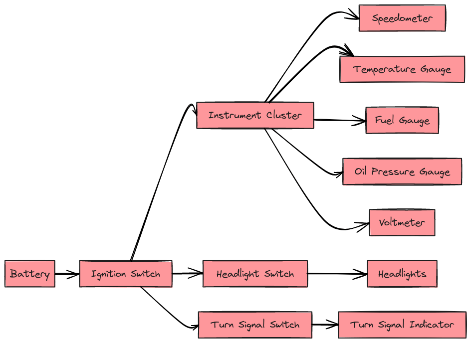
Diagram 3:
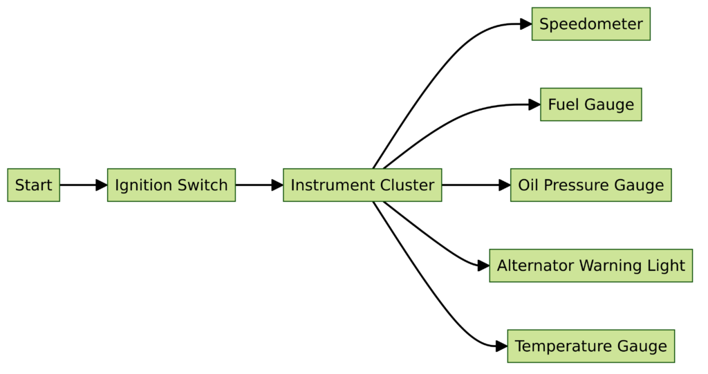
Diagram 4:

Where to Find 1979 F150 Wiring Diagrams Online?
Fortunately the Internet provides free access to Ford wiring diagrams spanning many years and models through communities of enthusiasts. Here are the best online destinations to find the correct schematic for your 1979 F150 instrument cluster:
Ford Truck Enthusiast Forums
On sites like https://www.ford-trucks.com/, you can browse model years to find complete manuals uploaded by members, containing the specific diagrams you need. There will often be PDFs showing both interior and engine bay wiring.
Other Forum Threads
By searching Google using keywords like “1979 F150 wiring diagram”, you can find forum threads on sites like TheRangerStation.com where people have shared download links or even diagrams photos.
OldFordTrucks.com
Another enthusiasts site called https://www.fordforums.com/ has image galleries organizing diagrams by truck part, like one specifically covering Instrument Panel Wire Schematics.
YouTube Videos
There are also some great YouTube channels that have created videos clearly showing how to access diagrams, like the Ford wiring handbook color codes.
The key is searching intelligently so you can find diagrams uploaded over the years in various places by Ford truck owners and mechanics.
Understanding the Different Diagrams
Once you access diagrams for your 1979 Ford F150, you’ll want to locate pages specifically showing the instrument cluster or dash wiring.
Here are a few key diagrams you may encounter:
Complete Wiring Manual
Full schematic manuals have 100+ pages covering all electrical systems. Search the table of contents or index for “instrument panel”, “IHC” or similar to find cluster wiring.
Instrument Panel Diagrams
These simplified diagrams only depict wiring for dash components like clusters, lighting, accessories. Critical for cluster-specific connections.
Engine Compartment Diagrams
Show wiring connections from front sensors, computer modules to interior clusters. Help trace sensor lines routed through firewall.
Component-Specific Diagrams
Individual diagrams for clusters, alternators, etc show more detail on their specific connectors.
Any of these will provide the info you need. Having the complete manual gives the full picture while individual diagrams offer more focused component views.
Instrument Cluster Wire Colors and Functions
The key to succeeding with your 1979 Ford F150 instrument cluster install or repair job is properly interpreting the wire colors, gauges, lighting and special connectors on its wiring diagram.
Here is what you’ll see on the diagram for your cluster:
Wire Colors
The main wires supplying power, ground and computer signals will be labeled with colors like:
- Red – Switched +12V Ignition Power
- Light Green – Dashboard Lights Power
- Black – Ground
- Dark Blue – Gauge Sensor Signal
Connector Pins
Wires connecting to your cluster plug into two rectangular plastic connectors. You must match diagram colors and pins.
Gauge/Indicator Markings
Diagrams label individual gauges like FUEL, TEMP, OIL as well as warning lights and info displays. Shows their power and sensor sources.
Having the correct colors and component labels ensures you don’t mix up connections. We’ll highlight some key hookups below.
Connecting Ignition, Lights and Gauges
With wire colors and gauge functions mapped properly from your diagram, you have all the needed info to connect your instrument cluster.
Here are some of the most essential hookups:
Ignition Power
Your diagram will route a red 12V wire that energizes the cluster gauges when you turn the key. This may connect directly to the ignition switch or splice with other accessories.
Dash Light Power
A light green wire connects to your headlight switch to power backlighting like gauge illumination and warning symbols. Ensures visibility when headlights activate.
Engine Sensors
Important sensor lines are:
- Dark blue – Coolant Temperature signal to Temp Gauge
- White – Oil Pressure switch to Oil Gauge
- Tan – Tachometer signal from Ignition Coil
With these wired correctly per your diagram, your cluster directly monitors engine operation.
Indicator Lights
Lights like Check Engine, Brake Warning and High Beams have power, ground and controller signal wires that must each connect properly.
The diagram keeps these and all other wires straight for easy installation.
Specific Diagrams Based on F150 Features
Wiring can vary on F150s equipped with certain features. Be sure to locate the correct diagram(s) if your 1979 Ford truck has:
Additional Gauges
Voltmeter – Measures battery/alternator. Needs connection to sensor wire.
Transmission Temp – Monitors transmission fluid temperature.
Pyrometer – For monitoring exhaust gas temperature.
Different Dash Configurations
Bench vs. Bucket Seats – Routing differences to switches and accessories.
Standard vs. Deluxe Interior – Extra gauges or indicators may be present.
Lighting Package – More backlighting wires & switch connectors.
Electronic Instrument Clusters
Later 80’s F150s switched to all-electronic digital displays. Extra computer signal wires.
Trailering/Towing Packages
Adds trailer battery voltage display, overdrive off indicator, brake wiring for trailers.
Having the correct diagram for your options ensures everything functions properly.
Using the Diagram to Troubleshoot Problems
If your 1979 Ford F150 instrument cluster or its gauges/lights begin malfunctioning, the wiring diagram helps significantly in troubleshooting and fixing issues.
Here’s how to diagnose problems:
Check Power and Ground Connections
Use a multimeter to test power and ground wires coming into the connector. If missing or fluctuating, check fuses, wiring condition and connections via the diagram.
Sensor Signal Issues
Dark blue sensor wires can be tested with a multimeter or test light to see if sending expected readings. If not, trace and inspect sensor connectors and wire condition per diagram.
Computer Signal Problems
If warning symbols illuminate erroneously, check connector pins from front computer modules to cluster for bent pins or faults using your diagram’s connector views.
Without the correct reference during repairs, it can turn into a game of endless guessing to fix your cluster issues. The diagram eliminates guessing.
Instrument Cluster Replacement
If replacing your malfunctioning instrument cluster completely, the wiring diagram is indispensable for smooth installation.
Whether installing a new factory cluster or aftermarket set of auto gauges, simply follow each wire coming into the old cluster via the diagram to replicate connections.
Key steps for cluster replacement:
- Carefully remove old cluster without damaging wires
- Connect replacement to existing wires by matching colors and pins
- Test all gauge operation and warning lights
- Troubleshoot any initial issues using diagram wiretracing
With a good diagram, cluster upgrade jobs take 1-2 hours vs. days of aggravation!
Expert Mechanic Tips for Your Ford Truck
We asked some professional mechanics familiar with Ford F150s to provide their best troubleshooting and wiring tips:
“Always visually follow each wire first to check condition before wiretracing with the diagram. Check common failure points like under dash, kick panels, hood openings.”
“Don’t assume wire colors – the previous owner may have spliced into something incorrectly. The diagram verifies which wire goes where.”
“For sensor issues, check connector fit/corrosion first, then electrical signal. Replace sensors as preventative maintenance.”
“With ignition problems, diagnose the starter circuit first using relay diagrams before moving to clusters.”
“A mechanics stethoscope is handy for finding shorts behind dash – just listen for arcing noises.”
Their experience saves you countless hours and avoids dangerous misdiagnoses. Combined with the correct schematic, you’ll be positioned for a smooth electrical repair or upgrade.
Conclusion – Getting the Most from Your 1979 Ford F150 Wiring Diagram
We hope this outlines the essentials of accessing and utilizing wiring diagrams for your 1979 Ford F150 instrument cluster and dash electronics.
The key points are:
- Diagrams are accessed online through forums and websites
- Understand diagram types – complete manual vs component specific
- Use wire colors, gauge markings and connectors during installation
- Check power, ground and sensor circuits when troubleshooting
Invest some time up front finding the best diagram resource you can for your truck. It will pay you back with a speedy and smooth electronics project.
And as always, don’t hesitate to consult a professional mechanic if you have any doubts during a major repair or modification. Your safety is most important.
Thanks for reading and best of luck with your 1979 Ford F150 instrument cluster upgrade or repair! Let us know in the comments if you have any tips to share from your own experience.

