Demystifying 1995 Ford 7.3 Powerstroke Engine Wiring Schematic
Have you ever opened the hood of your 1995 Ford truck with the 7.3 Powerstroke diesel engine and just scratched your head looking at that mess of wires and connectors? I’ve been there too. Anytime there’s an electrical issue like an inoperable fuel injector, bad sensor reading, or no start condition, having the proper wiring diagram is invaluable for troubleshooting. But those schematics can be intimidating to the uninitiated.
So how do you make use of the factory wiring diagram to understand the 7.3 Powerstroke’s electrical system and confidently complete repairs? Read on and I’ll demystify some of the key elements so you can get the information you need.
First we’ll cover ways to locate an accurate 1995 7.3 wiring schematic diagram from Ford or online sources. Next, we’ll highlight the essential electrical circuits and connections to comprehend. We’ll also walk through techniques for interpreting the diagram symbols and codes so you can trace wires from power source to component. Finally, we’ll outline some best practices for using the schematic to diagnose issues and complete harness repairs.
Armed with the right knowledge, you’ll go from head scratcher to wiring diagram master!
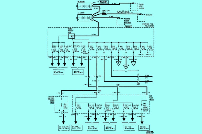
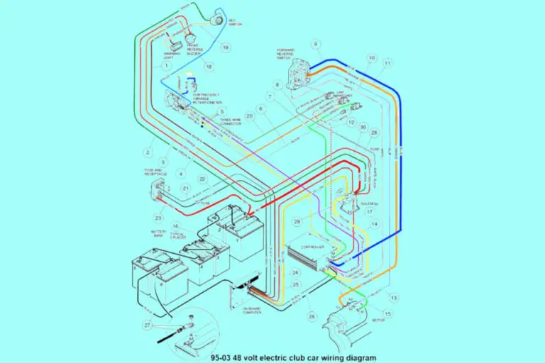
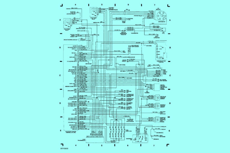
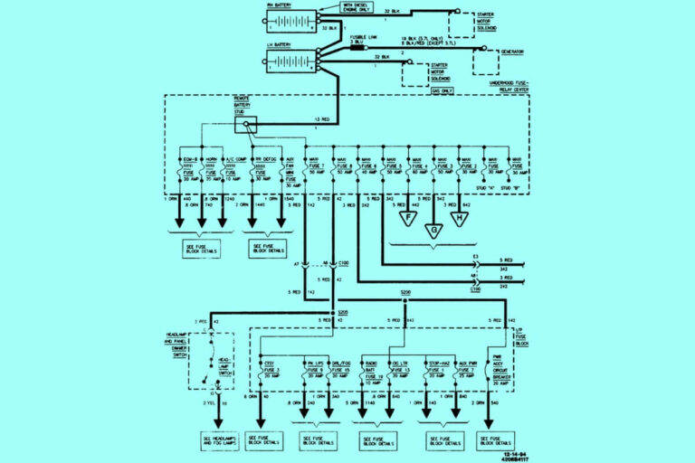
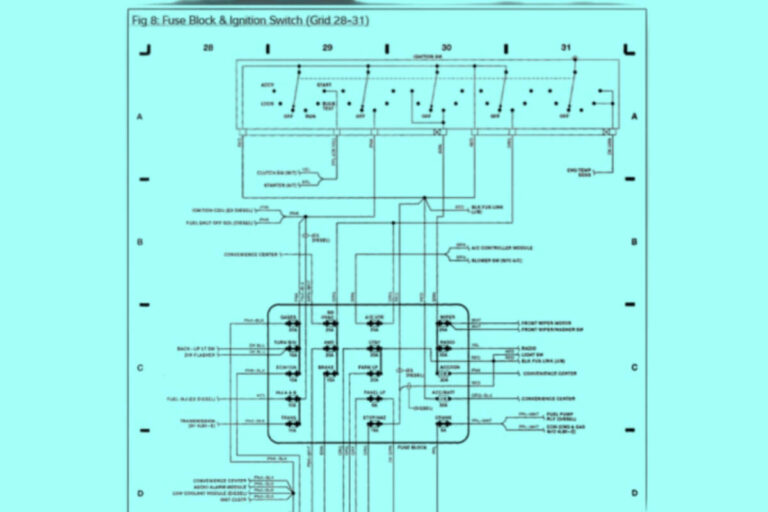
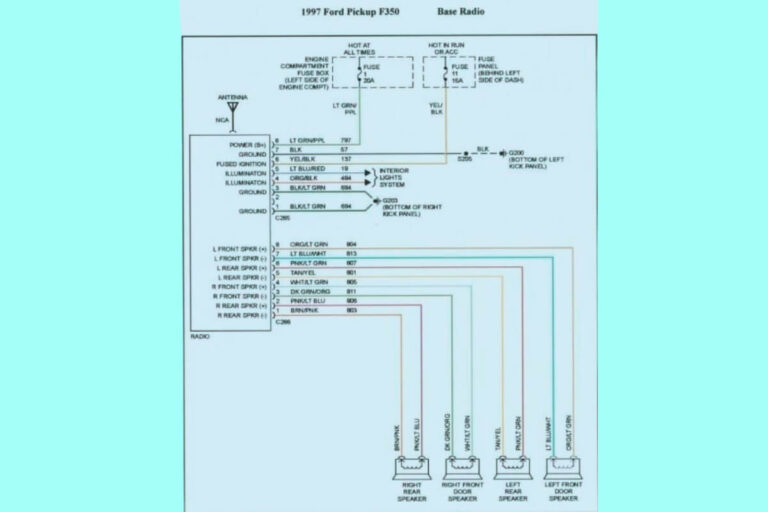
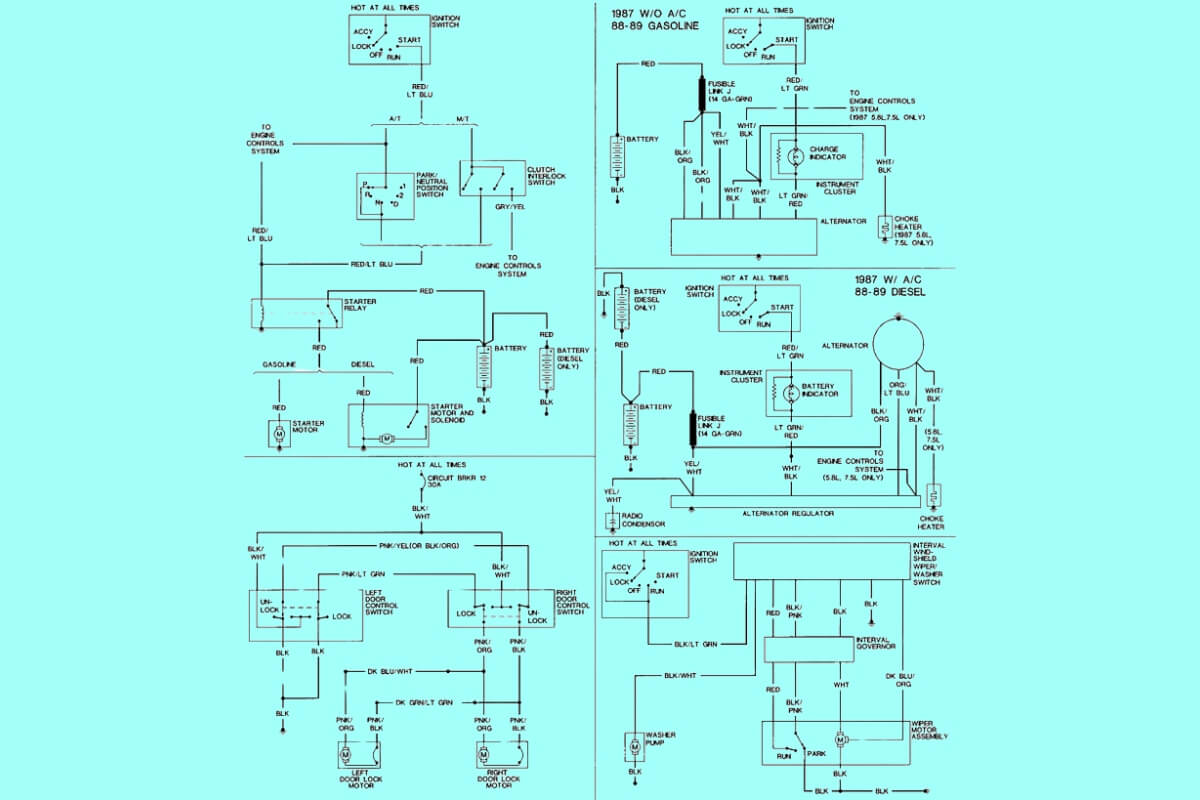
1995 Ford 7.3 Powerstroke Engine Wiring Diagrams
Diagram 1:
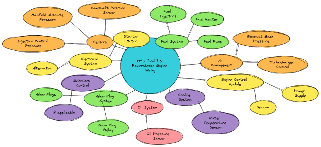
Diagram 2:
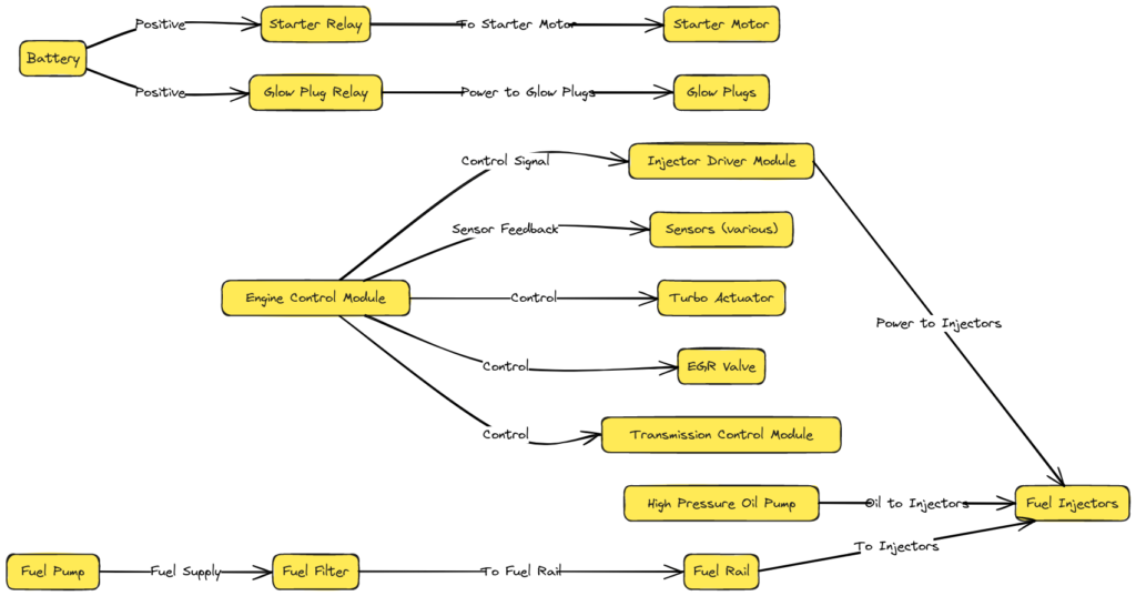
Diagram 3:
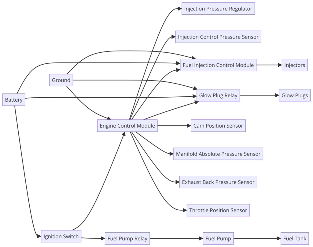
Diagram 4:
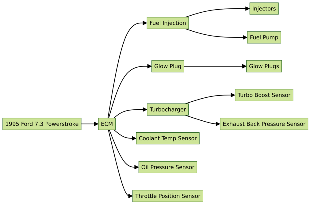
Diagram 5:

Where Do You Get the Wiring Diagram for a 1995 Ford Powerstroke?
Many 7.3 Powerstroke owners needing to understand the 1995 engine wiring harness go straight to the internet forums for help. And while you may find someone who has posted the complete schematic, that can be hit or miss. Instead, here are a few better options:
- Buy an OEM diagram – Check with your Ford dealer’s parts department. They may be able to print or order a copy of the factory 1995 wiring diagram for the engine or full truck. This is ideal but sometimes pricey.
- Get an online manual subscription – Multiple auto service sites like eAutoRepair provide official diagrams with convenient zooming and panning. Cost is reasonable for short term access.
- Search the diesel forums – While posting full factory schematics violates copyrights, some owners share snippets for specific areas that are handy reference.
- Use a repair database app – Mobile apps like ProDemand Wire Search aggregate wiring diagrams into a searchable database with handy highlighting tools.
Once you track down an accurate 1995 Powerstroke wiring diagram from a factory manual, you can dive into understanding the electrical system at a high level before using it to trace specific circuits or troubleshoot issues.
Essential Electrical Components and Circuits to Grasp
While a complete wiring schematic can be overwhelming initially, getting familiar with some of the key components and connections will go a long way for DIY repairs. Here are a few areas to focus on:
The Engine Control Module (ECM)
Also known as the PCM (Powertrain Control Module), this is essentially the truck’s on-board computer. It receives and processes signals from sensors to control timing, valve operation, fuel injection, and more. All engine operation wiring routes through the ECM in some way.
Crankshaft and Camshaft Sensors
These input the engine position and speed data needed for the ECM to pulse the injectors properly. The schematic will show the sensor power supply, ground, and output wires back to the computer.
Injector Wiring Harness
This connects all eight high pressure oil fuel injectors to the ECM. Each injector will have at least 2 wires – ground and trigger signal from the ECM telling it when to activate.
Various Sensors
These detect operating conditions like coolant temp, charge air temp, atmospheric pressure, etc. and feed signals back to the ECM. The diagram will show the sensor power and ground connections.
Fuse Boxes
These provide and distribute power protection for all the smaller wiring harnesses branching off it. The large battery junction box feeds smaller ones around the truck.
Instrument Cluster
This includes the gauges and warning lights in dashboard that relay information provided by sensors to the driver. The tachometer and “wait to start” indicator use information directly from the ECM for example.
How to Read and Interpret the Ford Wiring Schematic?
Once you have the full wiring diagram for the 1995 7.3 Powerstroke engine, or at least the section dealing with a problematic area, it takes some skill to properly interpret all the symbols, lines, codes, and labels. Here is a quick overview of the mapping concepts and how to trace a specific circuit.
Wire Colors and Gauges
Wires are shown with either a text label stating the color, an actual color background, or dots signifying striped lines. The diagrams also indicate wire thickness or gauge that is useful to match if splicing a repair.
Symbols
These small images represent components and connections without drawing every detail. With some study, you’ll quickly recognize icons for modules, grounds, specific sensors, switches, etc.
Connector Pin Identification
Where a wire terminates, you’ll see a label like “C224/P108”. This encodes the specific connector designation (“C”) and pin location to help track physical connections.
Circuit Tracing
You basically “follow the lines” through various intermediate connectors, splices, grounds and components. Identify the circuit start point, trace the path, interpreting all symbols along the way until you return to a ground or power source.
Troubleshoot Opens and Shorts
Check for wiring breaks or damaged insulation that may cause an open circuit. Look for points where bare wires may intermittently contact each other resulting in shorts. This is where carefully tracing and visualizing the circuit comes in handy.
Techniques for Diagnosing Electrical Issues
So when those gremlins pop up and you dive into the wiring schematic to diagnose, here are a few general troubleshooting techniques to help leverage the diagram most effectively:
- Use a multimeter to check continuity – Verify wires at various points along suspect circuit actually conduct electricity
- Check voltage drops across connectors – Differences may indicate excessive resistance from damage or corrosion
- Isolate components with problems – Bypass sensors or ECM circuits one at a time to aid diagnosis
- Consider an intermittent issue – Use diagram to identify spots where movement or vibration could make temporary contact
- Always check grounds and power at each component – Even good wires can have bad connections!
- Think end-to-end – The diagram shows how everything interconnects so you can better pinpoint root cause.
Don’t forget to utilize factory service manuals as well for detailed diagnostics procedures specific to codes or symptoms. But the wiring schematic should be referenced alongside to visualize how test points relate.
When Do You Need to Repair or Replace Wiring?
If during your troubleshooting you identify physical damage like rubbed through insulation or corroded terminals that are impacting circuit function, the corresponding wires obviously need repair. Here are also a few other scenarios where wiring replacement commonly comes up on old diesel trucks:
- Engine replacement – Swapping to a different model likely requires wiring harness modifications
- Major restoration – Upgrading the engine bay is a good opportunity to replace aged wires
- Rats nest wires – Prior owners’ hack repairs result in a mess needing complete replacement. Don’t assume function!
- Upgrading sensors – Later technology sensors often necessitate new compatible wiring with different connectors or pins.
Replacing the full engine wiring harness or any subsection is no small task. Careful labeling during removal, getting the correctly configured replacement harness, and taking precautions during installation are all vital for success. Having the factory diagram as reference during the process reduces chances of overlooking something too.
Additional Help from Ford or Diesel Mechanics
Even armed with the wiring diagram and repair manual, tracking down intermittent electrical gremlins or completing complex harness replacement jobs is often best left to experienced professionals. Seeking assistance can save major headaches in some instances. Here are few options if you hit roadblocks:
- Have your local Ford dealer consult factory service diagrams and documentation that hobbyists won’t have access to. Their master technicians can interpret and even edit diagrams.
- Utilize independent shops specializing in diesel repair. Their expertise specifically with Ford Powerstroke Wirediagrams combined with specialized diagnostic capabilities may pinpoint ECM faults you can’t identify in your garage.
- Post questions on owner forums to tap into collected wisdom fixing old 7.3l wiring. Include photos and diagrams of your specific issue for best insights. Crowdsource what your stuck on.
Getting quality help upfront can prevent wasting money on parts changing that have no impact or experiments that leave your truck immobilized.
Key Takeaways for Leveraging 1995 7.3 Powerstroke Wiring Diagrams
Hopefully this overview better prepares you to locate the correct 1995 7.3 Powerstroke wiring schematic and leverage it to maximum benefit for repairs and troubleshooting engine electrical issues. Here are the key takeaways to remember:
- Factory Ford wiring diagrams from service manuals are essential for accurate troubleshooting
- Focus first on understanding key components like the ECM, sensors, and fuse boxes
- Properly interpreting the diagram symbols, connector pin IDs, wire routing and colors takes practice
- Changes in voltage drops, continuity checks, and isolation tests aid electrical diagnosis
- Match wire gauge, connectors, and configuration when splicing or replacing wire sections
- Consider getting professional assistance for complex issues or wiring jobs
Armed with the right schematic and some fundamental wiring skills, that nest of colored lines and intimidating symbols transforms into a helpful map for conquering your next diesel wiring adventure! Let me know in the comments if this overview gave you more wiring diagram confidence or if you have additional tips for leverage schematics on old Ford trucks. Happy wrenching!

