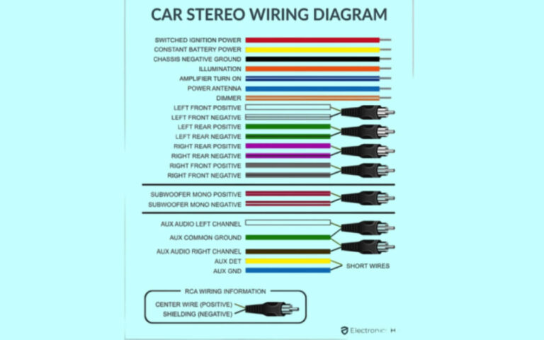
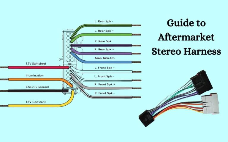
Demystifying Dual Radio Wiring Diagram
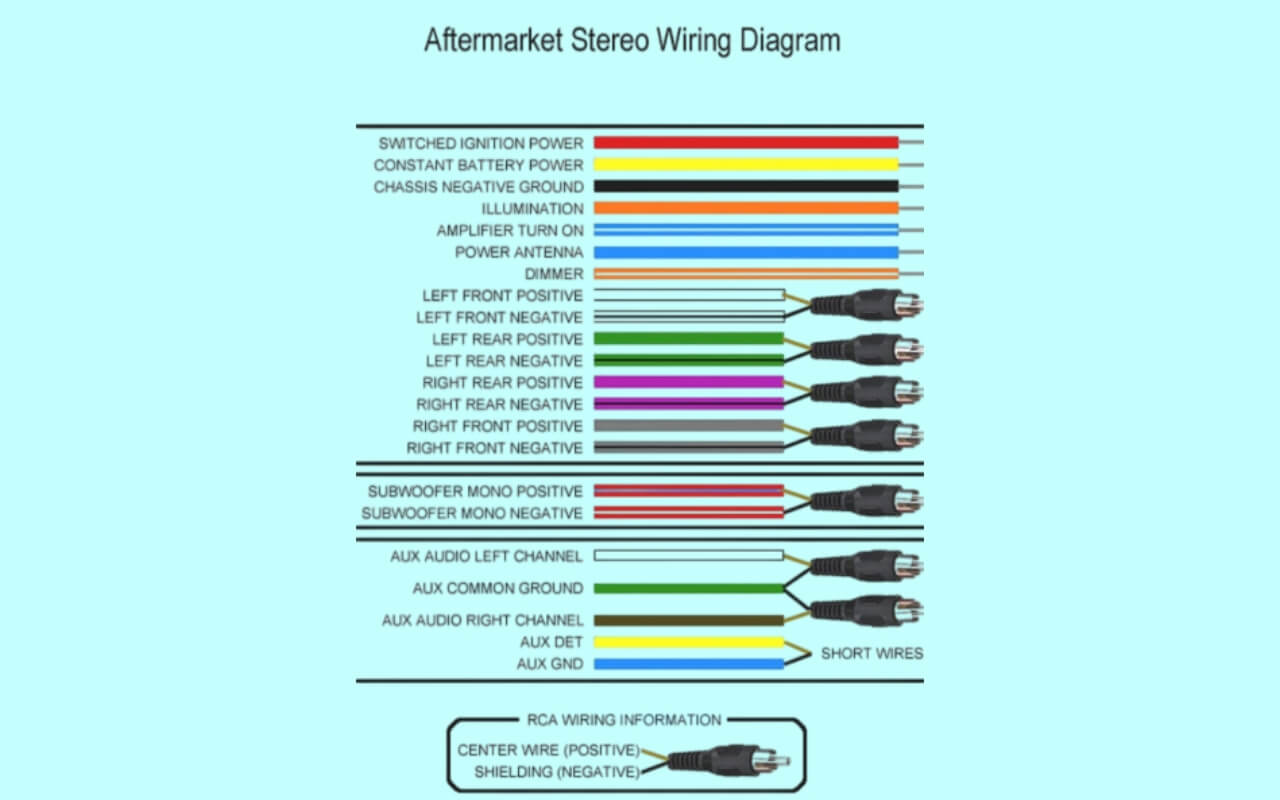
Have you ever opened your car dash and stared in confusion at a mess of colored wires? Or begun an installation project only to realize you don’t understand the wiring diagram?
You’re not alone. Learning to work with car electrical systems can feel overwhelming. Installing a new stereo, speakers, or other gadgets often requires decoding complex diagrams full of symbols and color codes.
What if you could easily read any car stereo wiring diagram? This guide will explain exactly how to understand dual car stereo wiring, identify each wire’s purpose, safely connect new equipment, avoid damaging your vehicle, and complete installations like a pro.
We’ll cover:
- Key facts about wiring diagrams
- How to read and interpret diagrams
- Gathering information before installing
- Step-by-step stereo installation tips
- Dual car stereo wiring specifics
- Common color code conventions
- Troubleshooting tricks
- Additional helpful resources
Let’s get started demystifying complicated car stereo wiring diagrams once and for all!
Dual Radio Wiring Diagrams
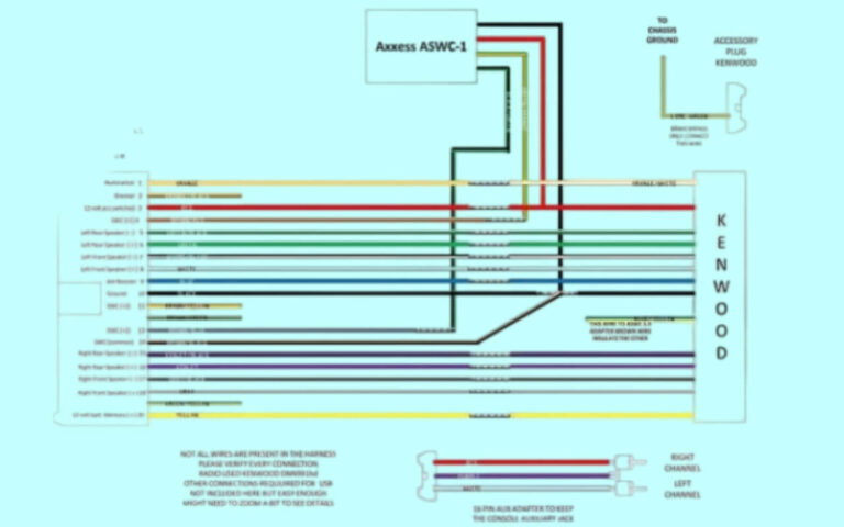
Diagram 1:
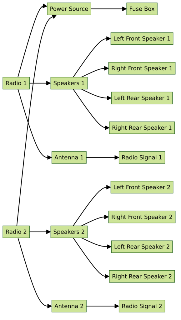
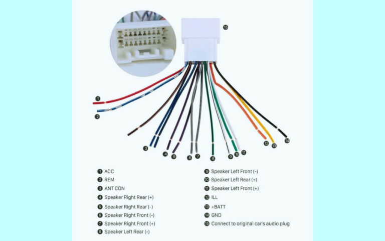
Diagram 2:
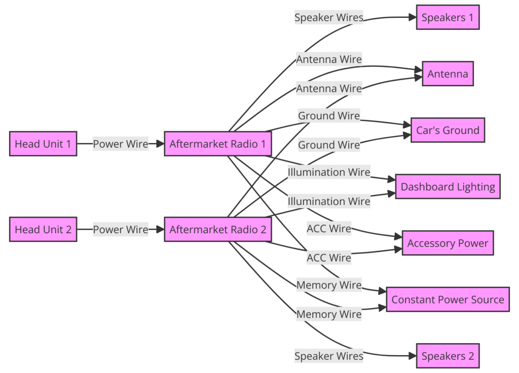
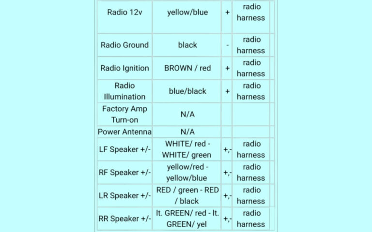
Diagram 3:
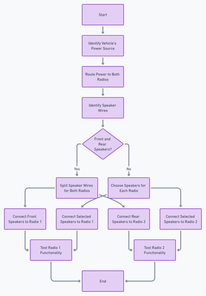
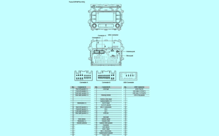
Diagram 4:
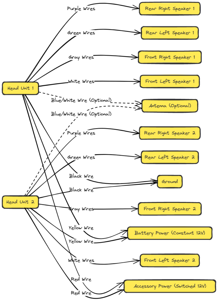
Diagram 5:

The Purpose of Car Stereo Wiring Diagrams
A car stereo wiring diagram is a simple visual representation of all the connections required to wire a vehicle for a car stereo or other electronic component. Diagrams cover diverse vital equipment like:
- The car stereo itself
- Speakers
- Video displays
Wiring diagrams serve several key functions:
- Aid installation: Diagrams enable proper electrical connections between complex vehicle systems and aftermarket gear without errors.
- Prevent damage: They help installers avoid accidentally connecting wires improperly which can destroy expensive stereos or vehicle components.
- Troubleshoot issues: Diagrams facilitate investigating wiring to identify and correct problems.
In short, these critical blueprints save installers time, money, and major headaches!
Understanding how to read and modify diagrams is an essential skill for successfully upgrading a car’s electronics.
Interpreting Car Stereo Wiring Diagrams
At first glance, a wiring diagram seems complicated – just a jumble of symbols, colors and text.
Learning a few fundamentals makes diagram interpretation simple:
Symbols
Diagrams utilize standard symbols to represent components. Common symbols include:
- Lines or arrows: Wires connecting devices
- Oval: Electrical connector
- Square box: Electrical device
- Circle: Connector pin
- Diamond: Sensor
With some practice these convey connections between equipment.
Wire Identification
Determining a wire’s purpose requires identifying attributes:
- Wire color
- Text label
- Location at device connector
- Signal type (audio left/right, power, etc.)
For example, a “blue wire labeled ‘Power’” likely provides +12V power.
Connector Pinouts
The wiring order of device connectors appears in diagrams. This “pinout” maps wires entering each pin.
Connector views assist properly plugging in gear.
With basic symbols and conventions understood, diagrams become easier to navigate!
Gather Crucial Information Before Installation
Before touching wires, collect details needed to safely install electronics:
Vehicle Wiring Reference
Consult the vehicle owner’s manual for:
- Fuse box location
- Factory wiring diagrams
- Component data (recommended fuses, wire gauges, amperages, etc.)
This provides an invaluable reference for ensuring compatible connections.
Gear Specifications
Record specifications printed on devices:
- Power requirements
- Input/output signal formats
- Wire color-coding
Spec sheets optimize component interfacing.
Tools
Assemble standard installation tools like:
- Wire crimpers
- Cable stripper
- Volt meter
- Soldering iron
Bonus specialty automotive tools can also help considerably.
With these ready, moving wires becomes easy.
Now let’s walk through installation from start to finish…
Step-By-Step Car Stereo Installation Guide
Once information gathering is complete, the real installation work begins:
Safety Checks
Adding or replacing vehicle electronics risks hazardous mistakes like:
- Damaging car computer systems
- Overloading electrical circuits
- Improperly grounded components
So first address basics:
- Disconnect the negative battery cable – Prevents shorts that can destroy electronics prematurely
- Check condition of existing wiring – Repair any damaged wires
- Corrosion
- Bad splices
- Damaged insulation
- Confirm no vacuum lines/moving parts interfere behind the dashboard
Safety first!
Stage Wiring
Next, prep new wiring before connecting to the car:
- Insert device connectors
- Attach power adapters
- Customize lengths for a clean install
Staging reduces installation workload.
Connect Cables
Now wire components per diagram specifications:
- Match all wire colors precisely
- Affix signal cables to proper input/output pins
- Secure power wires complete circuits (always red to positive, black to vehicle ground)
- Tie into vehicle 12V+ lines at the fusebox
Double check connections to avoid mistakes.
Post Install Testing
Before buttoning up the dash, carefully test operation:
- Verify speaker channels with audio output
- Check system voltage margins at high volume
- Ensure cables don’t pinch or rub
Catch flaws early to facilitate corrections.
And enjoy your tunes!
Key Facts About Dual Car Stereo Wiring
We’ve covered the fundamentals – now let’s discuss dual car stereo wiring intricacies.
As vehicles evolve to support more technology, factory dash openings expand allowing “double din” stereo units accommodating large touchscreens or multiple components.
Common dual car stereo wiring concerns include:
More Wires
Larger faceplate openings permit integrating complex receivers alongside other gear like:
- Satellite radios
- Carputer tablets
- Bluetooth handsfree speakerphones
This enables superior functionality but requires properly routing the rat’s nest of wiring between chained devices.
Multiple Signal Standards
Bridging equipment with different connectivity is challenging:
- Analog RCA
- Digital coaxial S/PDIF
- Optical TOSLINK
Converters may be essential for compatibility.
The additioinal cables and configurations make wiring management critical.
Car Stereo Wiring Diagram Color Code Standards
Why are car electrical diagrams color-coded?
Standardized wire colors speed installations by clearly identifying distinct vehicle circuits and incoming aftermarket signals at a glance.
Commonly accepted color conventions include:
Power
- Red – +12V constant battery/ignition power
- Yellow – +12V switched/accessory power
- Black – Ground (-)
Speaker Channels
- White – Front left +
- White/Black – Front left –
- Gray – Front right +
- Gray/Black – Front right –
- Green – Rear left +
- Green/Black – Rear left –
- Purple – Rear right +
- Purple/Black – Rear –
Controls
- Blue/White – Power antenna
- Blue – Amplifier remote turn-on lead
- Brown – Parking lights
And many more exist. Consistency aids professionals matching vehicle harnesses.
But what if equipment lacks diagram color coding?
Connecting a Car Stereo Without Wire Colors
Occasionally car stereos omit color-coded wiring diagrams due to unexpected standardization gaps.
Lacking assignments, identify wires experimentally using:
DMM Electrical Tests
Use a digital multimeter (DMM) to trace circuits:
- Check for +12V on red, yellow and orange wires to locate constant and switched power.
- Verify speaker channel pairs with continuity tests.
- White may run left channels
- Gray operate right side speakers
- Measure DC resistance acrossspeaker wires to detect +/- polarities
Manual Signal Tests
Temporarily activate components to identify connections:
- Power on the unit without permanent installation
- Manually click amplifier remote lead
- Often blue wire activates amp
- Operate buttons and controls to detect function
Tedious but effective!
Now let’s answer some common car stereo wiring questions.
Frequently Asked Car Stereo Wiring Questions
Here are some typical pain points encountered when decoding wiring diagrams with solutions:
Why doesn’t my new car stereo turn on?
Check for +12V constant and switched power input. Verify the head unit receives electricity by measuring voltage across red & yellow wires at connectors.
What does the black ground wire connect to?
Find a metal grounding screw on the vehicle body, often located near the fusebox. Or connect wiring harness black wire directly to the negative battery terminal. This safely earth grounds components.
Can I use the factory amplifier with an aftermarket stereo?
Possibly – some amplifiers won’t function without proprietary vehicle data signals. Confirm amplifier compatibility and wiring requirements to leverage factory audio hardware.
Where can I source a car stereo wiring harness adapter?
Many auto parts stores stock wiring harnesses that splice new car stereos into factory connectors. This avoids cutting OEM vehicle wires. Adapters are also available online from retailers like Amazon and Crutchfield.
Got an installation roadblock? Don’t hesitate to use installation manuals or consult a professional!
Additional Helpful Car Stereo Wiring Diagram Resources
Hopefully this guide covers the basics demystifying wiring diagrams!
Some additional handy references:
- Crutchfield Car Stereo Wiring Guide – Tutorials and gear recommendations from respected retailer Crutchfield
- [Online Automotive Wiring Diagrams](https://wiring diagrams.com/) – Enormous database of automotive wiring content covering most vehicle makes and models
- Mobile Installation Pros – Nationwide car stereo installation service for anyone needing expert help
And don’t overlook your car manual – the factory wiring diagrams often contain essential details!
Review the key topics covered:
- How to interpret car stereo wiring diagrams
- Crucial steps preparing for installation
- Connecting new stereos properly
- Dual car stereo wiring intricacies
- Common color coding conventions
- Solutions for frequent wiring troubles
- Additional useful educational resources
We wish you safe travels on your car audio installation journey! May all your car stereos connect easily and bump tunefully thanks to handy wiring diagrams!

