Demystifying Kenwood Car Stereo Wiring Diagrams
Have you ever opened up your car dashboard and stared in confusion at the mess of wires behind your car stereo, wondering how on earth to connect your slick new Kenwood head unit? Do those multicolored kenwood wires and connector plugs seem like a puzzle with no solution in sight?
How can you make sense of tangled wires and actually connect a Kenwood stereo by yourself?
The good news is understanding car stereo wiring diagrams is simpler than it looks! With this complete guide on Kenwood wiring diagrams, harness connectors, wire colors, and step-by-step installation instructions, you’ll be rocking out to your new car sound system in no time.
Here we will cover everything you need to know about:
- Reading Kenwood wiring diagram code and deciphering wire colors
- Finding the correct wiring diagram for your Kenwood receiver
- Basic explanations of Kenwood car audio terms and connections
- A walkthrough of wiring harness and dash kit installation
- Troubleshooting common Kenwood stereo wiring problems
- Pro tips for clean and tidy wiring
Equipped with the knowledge this post provides on Kenwood head unit wiring, those confusing install diagrams will transform into easy-to-follow road maps!
What is a Kenwood Wiring Diagram?
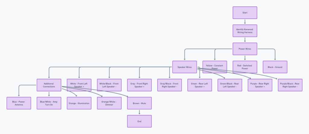
A Kenwood car stereo wiring diagram is a simple visual representation of what cables connect to which ports on the back of your head unit. The diagram shows different wire colors and connectors and what each needs to plug into, acting as a guide for proper installation.
Kenwood wiring diagrams serve a few key purposes:
- Allow DIY installers to properly match up connectors and harness cables
- Ensure correct wiring which avoids damaging components
- Prevent incorrectly crossed wires or backwards connections
- Guarantee speakers, amplifier output channels, and other hardware sync up properly
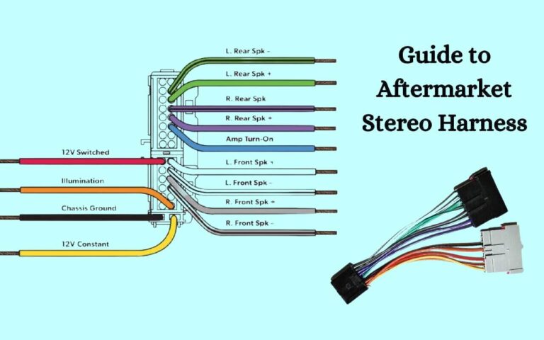
As you see above, Kenwood diagrams color code the necessary wires and ports and include shorthand text to indicate the component being connected. This makes it quick and easy to match up the right cables during installation.
Kenwood Car Stereo Wiring Diagrams
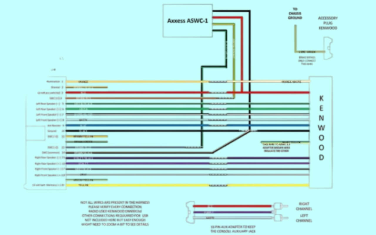
Diagram 1:
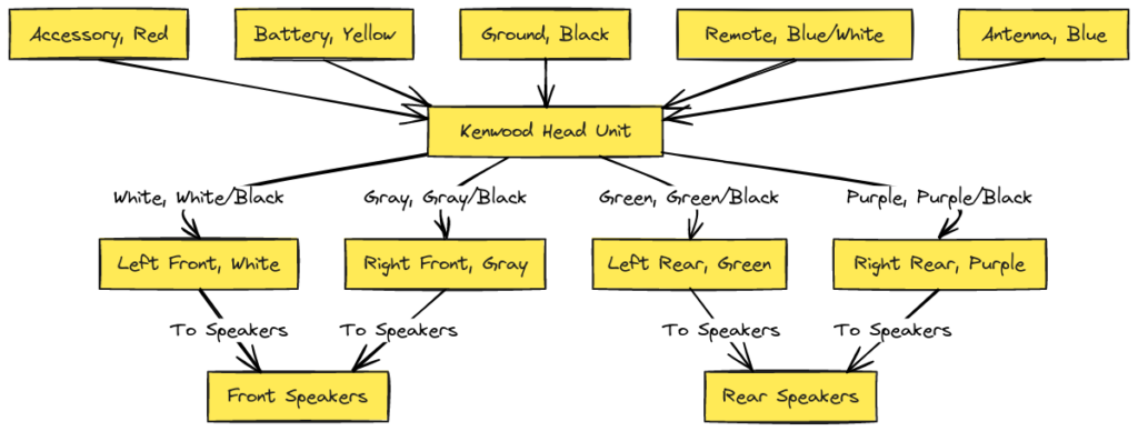
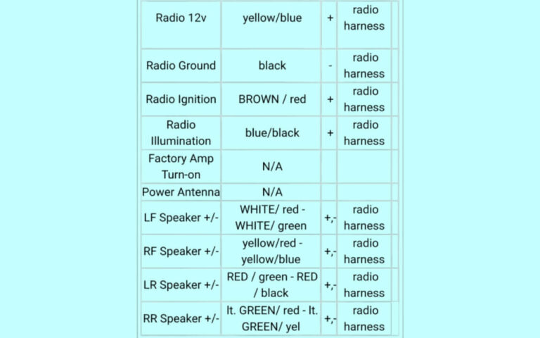
Diagram 2:
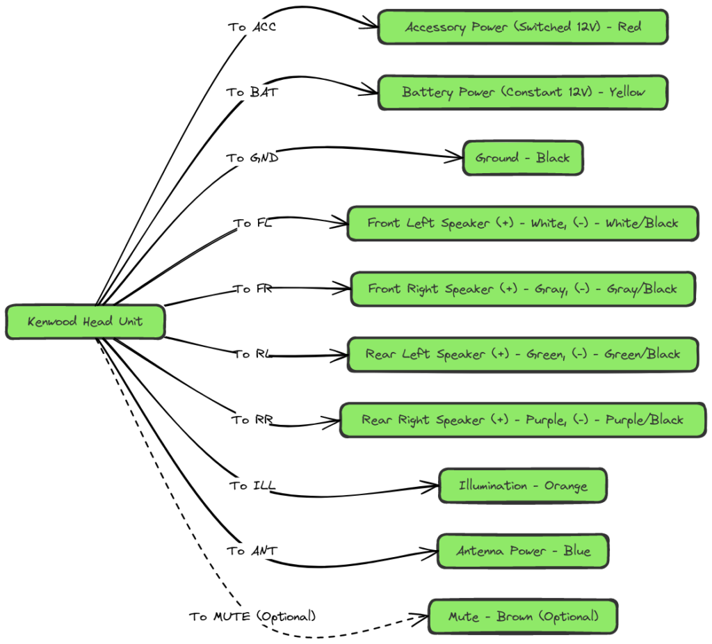
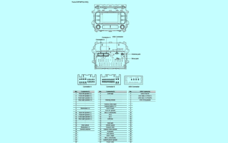
Diagram 3:
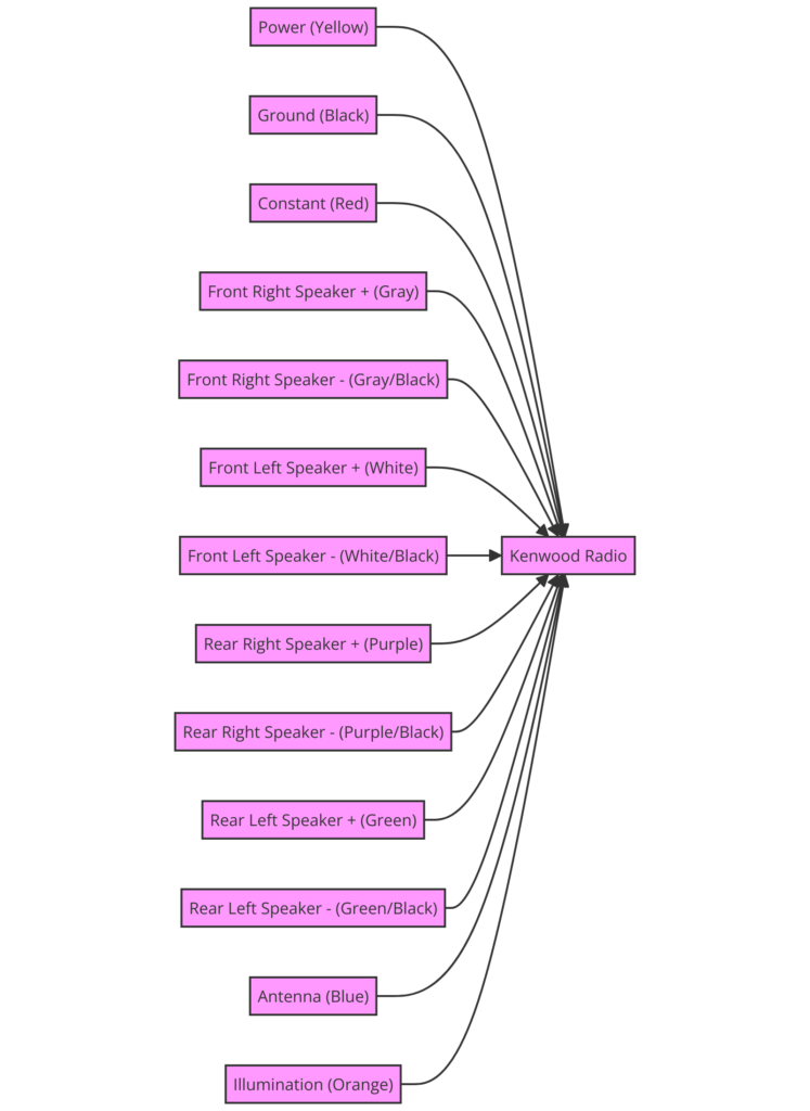
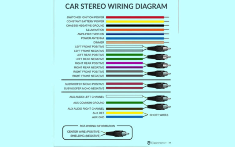
Diagram 4:
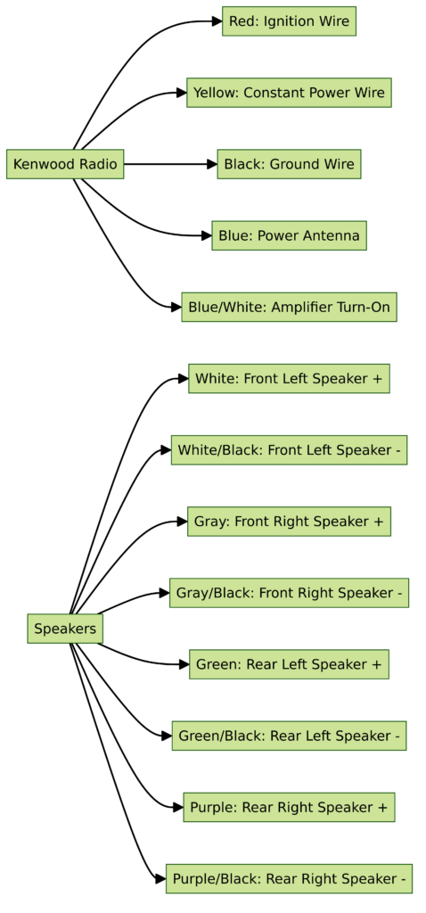
Diagram 5:
Why Do You Need a Kenwood Wiring Diagram?
Is it possible to install a Kenwood head unit without using the car stereo wiring diagram? Technically yes, if you randomly guess which wires and ports align. But that trial-and-error process can easily result in:
- Blown fuses from crossed power cables
- Electrical shorts damaging the stereo
- Speakers wired out of phase and muddled audio
- Burned out amplifiers or speakers from impedance mismatches
Using the Kenwood wiring diagram ensures proper electrical connections which delivers clean, robust audio to your speakers without damaging components.
Additionally, the diagrams prevent you from needing to take extra time redoing wiring. Following Kenwood pinouts precisely the first time allows completing installations much quicker.
How to Read a Kenwood Stereo Wiring Color Code
Learning to read Kenwood wiring diagrams starts with deciphering the colors and markings on each wire. Let’s take a look at the meaning behind common Kenwood cable color codes and labels:
- Red wire – Indicates main positive 12V constant battery/ignition power
- Yellow wire – 12V switched power only on when ignition is on
- Black wire – Ground wire which completes all circuits
- Blue wire with white stripe – Power antenna activation lead
- Blue – Used for amplifier or Antenna control remote lead-in
- White – Left front + speaker output channel
- White with Black stripe – Left front – speaker output channel
- Gray – Right front + speaker output channel
- Gray with Black stripe – Right front – speaker output channel
- Green – Left rear + speaker output channel
- Green with Black stripe – Left rear – speaker output channel
- Purple – Right rear + speaker output channel
- Purple with Black stripe – Right rear – speaker output channel
Kenwood head units will have various ports corresponding to functions like Rear Camera Input, Steering Wheel Control Input, RCA Audio Output channels, etc. Wires connecting to these ports will have abbreviations like SWC, REAR CAM, SUBWOOFER, or FR- (front right). These labels indicate which component the wire leads to.
So in summary, Kenwood wires use colors and labels to show connections to vehicle power, ground, speakers, antenna, amps, steering wheel controls, and other devices. The diagrams show exactly when to use each.
Finding the Right Kenwood Wire Diagram for Your Car
Since Kenwood wiring pinouts differ between car receiver models, you need the correct diagram that matches your head unit. Here are some tips for locating the right Kenwood car stereo wiring guide:
- Check manual – Open up the manuals and paperwork that came with your Kenwood device. Frequently an install diagram is included.
- Search online – Use the specific model # like “Kenwood KDC-X704 wiring diagram”. Add your car make and year as well.
- Multi-model diagrams – Sites like ModifiedLife often have diagrams covering numerous Kenwood models for common vehicle makes.
- Video install guides – YouTube videos for your specific head unit show wire colors when connecting during installs.
- Installer forums – The 12 Volt and Install Dr are tech forums with details on wiring various aftermarket stereos.
- Call Kenwood support – As a last resort, call Kenwood customer support and inquire whether they can email you the exact wiring diagram.
Having the precise Kenwood car entertainment system wiring diagram is crucial for seamless installation. With the abundance of resources online, you should be able to source the correct one for your model and vehicle.
Understanding Kenwood Speaker Wiring
Connecting your new stereo to car speakers requires working with speaker output channels and various speaker wires. Here is some key information that will make speaker wiring effortless:
- Standard aftermarket head units have four speaker channel outputs – Front Left, Front Right, Rear Left, Rear Right. Four speakers can directly connect to the receiver
- Two sets of positive and negative wires exists per channel, normally represented by colors mentioned previously
- “Live” wires leading from the Kenwood unit need to connect to positive speaker inputs
- “Grounded” wires leading from the Kenwood need to connect to negative speaker wire inputs
- To avoid speaker damage, use speakers with impedance equal or greater than the Kenwood unit’s rating
- If installing amplifiers, connect RCA output cables from the Kenwood into amplifier inputs
Ensure your speaker output channels correspond properly to the car speakers. The Kenwood wiring diagrams will specify optimal assignments.
Step-by-Step Kenwood Car Stereo Wiring Installation
Once you have your wiring diagram handy, follow these tips for smooth installation:
Car Stereo Wiring Harness:
- Begin by disconnecting your car battery negative terminal to avoid electrical shorts
- Locate the factory wiring harness connector in your dash and unplug it from the back of the factory radio
- Plug the male side of your new stereo wiring harness into the Kenwood female connector
- Test the harness connector fits by plugging it into the Kenwood stereo
- Ensure you have the polarization matched up properly between connectors
Running Power, Signal, Speaker Wires:
- Attach the ground black wire coming off the aftermarket harness to a metal screw or bolt attached to the vehicle chassis using a ring terminal connector
- Run the 12V constant red power wire through your firewall by an existing grommet into the interior fuse box. Connect to an open slot properly rated for the amperage draw of your stereo. Install an additional fuse into the wire if desired.
- If utilizing, connect the 12V ignition/switched yellow wire to an open ACC slot or wire in the fuse box
- Connect the backup camera RCA or other RCA wires to the new head unit
- Using your wiring guide, connect the color coded harness speaker wires leading from the stereo by matching them properly to the vehicle’s speaker pigtails. Ensure positive connects to positive, negative to negative.
- Place all wires away from moving parts or heat sources, use grommets when running wires through metal
- Connect battery terminal securely and test stereo operation
Take the process slow, double check all connections match the diagram, and neatly position wiring for a safe install.
Diagnosing Kenwood Stereo Wiring Problems
In case you encounter issues getting sound or other electrical gremlins, here is how to troubleshoot Kenwood wiring:
- No Power – Check all connections at the battery and fuse box. Test wires with a multimeter for voltage. Inspect all fuses.
- Blown Fuse – Disconnect components one by one until short is isolated. Analyze connections for pinched wires or exposed positive/negative touching metal chassis.
- Speakers Not Working – Confirm speaker wires have a solid connection with no corrosion or shorting. Test speakers individually with known good wires.
- No Sound From Some Speakers – Likely wiring crossed on one side. Double check each speaker output channel connects to the proper speaker.
- Alternator Whine – Ensure ground wire has clean contact to metal body. Search for shorts in RCA wires or cap off open RCA ends. Add ground loop isolator.
- Display Works But No Audio – Potential faulty head unit. Check internal fuse, settings, source selection, and static on radio stations.
Checking over the basics like connections, shorts, fused power wires, ground contacts, and individual speakers can help narrow down Kenwood wiring difficulties.
Expert Tips for Clean Kenwood Audio Wiring
Achieving a professional looking installation includes correctly running wiring through the dash and interior panels. Here are some pro guidelines:
- Plan wire routing from the head unit space through cutouts before permanently mounting
- Bundle wires together with electrical tape or wire loom
- Ensure wires avoid rubbing on sharp metal edges by using grommets and wire conduits
- Use zip ties, wire ties, twist mounts to neatly secure harness bundles against vehicle body panels
- Mount amplifier/crossover components securely to limit vehicle rattling noises
- Separate all speaker, signal, and power cables away from each other when possible
- Double check wires are not strained when dashboard components get reattached
Completing these extra steps leads to eye pleasing wire results plus reduced noise issues and loose shorts down the road.
Frequently Asked Questions about Kenwood Car Stereo Wiring Diagrams
As a recap, here are answers to some of the most common questions DIY installers have about using Kenwood wiring pinouts:
Do the wire colors always match between car stereo diagrams?
While fairly standard, some variance can exist between models. Always follow wiring exactly as laid out in the particular diagram for your Kenwood device.
Can I connect speakers directly to the head unit or do I need an amplifier?
Four standard speakers can directly wire to modern Kenwoods without requiring an additional amp. But amplifiers allow powering extensive car audio systems.
What is the difference between constant and switched power wires?
Constant 12V red wires remain energized even when ignition is off, keeping memory intact. Switched 12V yellow wires turn on/off with ignition key preventing battery drain.
Why won’t my new stereo turn on?
Check for an incorrectly wired yellow or red wire. Confirm all ground connections are solid. Inspect wiring for damaged casing exposing power/ground resulting in shorts.
How do I add satellite radios, backup cameras and steering wheel controls?
Look for special harness adapters that splice into wiring providing ports to plug in steering wheel control buttons, RCA cables for cameras/satellite radio boxes.
Conclusion
If you made it this far, congratulations – you now have all the necessary skills to decipher Kenwood wiring diagrams like a pro!
The key to conquering intimidating install diagrams is having the right reference materials specific to your Kenwood car entertainment receiver.
Equipped with handy instructions tailored to your model, connecting wires and connectors correctly is smooth sailing.
Finally, adhering to solid wiring practices when running and securing cables keeps your handiwork intact for years beyond the job.
Soon you will reap the rewards cranking out the hot new sounds. So use this guide to wire up that Kenwood head unit like an expert!

