John Deere D140 Wiring Diagram: A Visual Guide
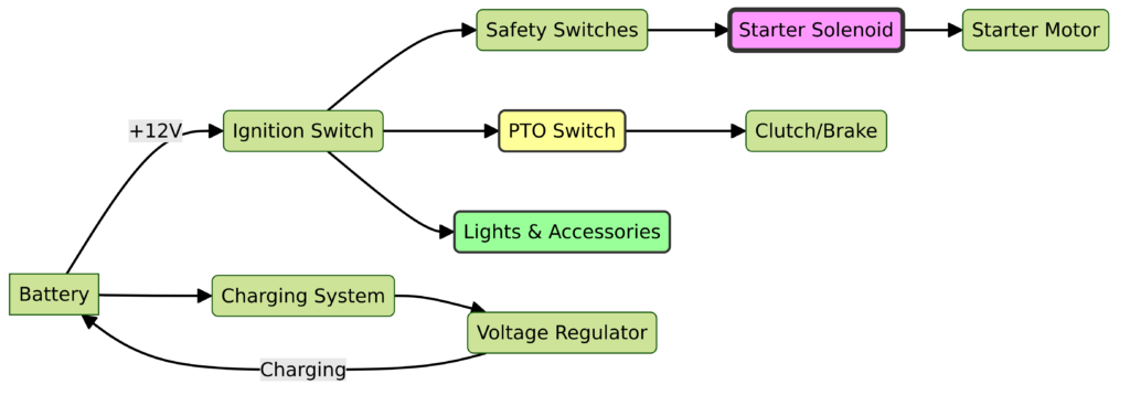
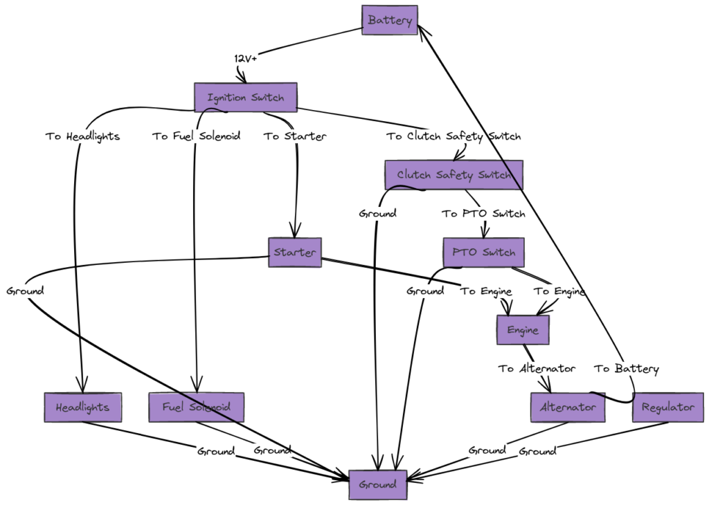
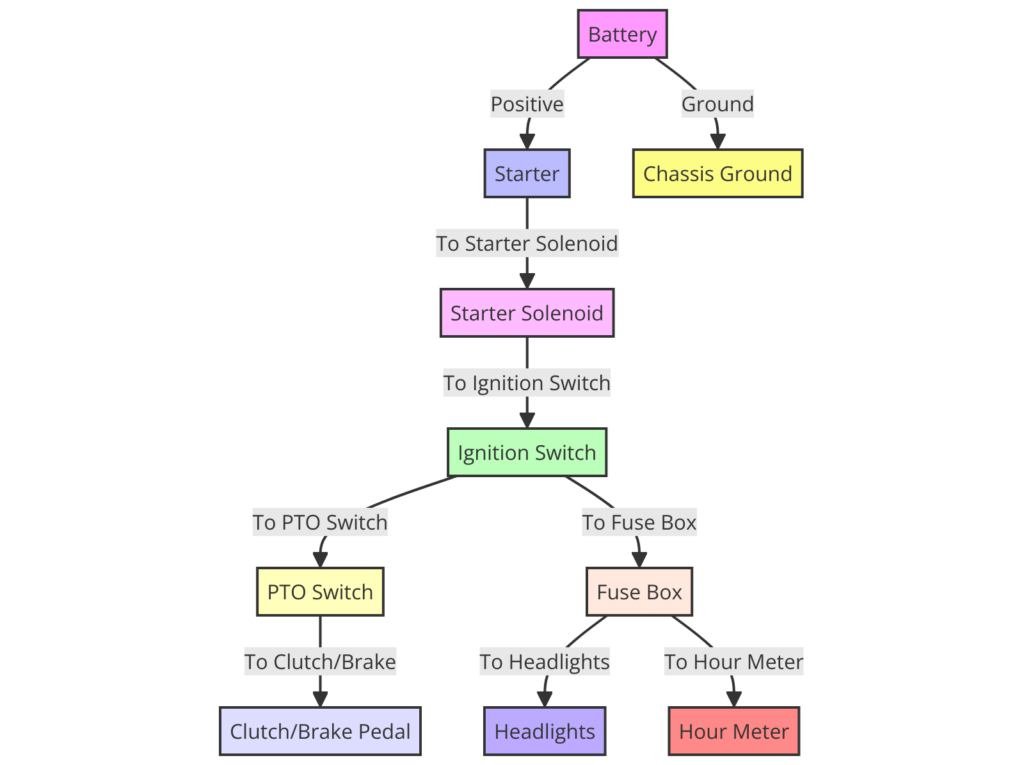
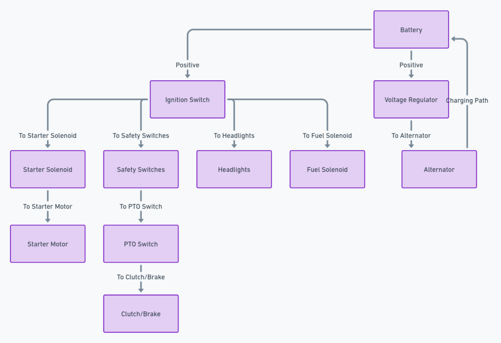
The wiring diagram or schematic outlines the complete electrical system of the D140 tractor model. It is like a road map showing how power flows through the various fuses, relays, switches, sensors, lights, attachments, and other components via color coded wires and connectors.
Understanding this visual diagram is essential when troubleshooting electrical faults, planning installations of accessories like LED lights or stereo systems, tracing specific circuit paths, and ensuring proper cable routing. It enables tracing electrical power from the battery to each part needing electricity to function.
John Deere D140 Wiring Diagrams
Diagram 1:

Diagram 2:

Diagram 3:

Diagram 4:

Diagram 5:

What’s Included in the John Deere D140 Wiring Diagram
The D140 wiring diagram includes both main wiring harnesses/looms and attachments:
- Main harness – connects the essential systems like starter motor, alternator, lights, panel, safety switches etc.
- Engine wiring – sensors, ignition coil, fuel shut off solenoid
- Dash panel wiring
- Accessory power circuits
- Lighting circuits – headlights, turn signals
- Non-electrical attachments
Additionally, the schematic provides vital information through symbols/codes, connector pinouts, splice locations, grounds, voltages and more. Wire colors and gauge sizes are also depicted.
How to Read the John Deere D140 Wiring Diagram
When initially glancing at the diagram, it may seem complicated with so many colored lines and symbols. But using basic techniques makes deciphering much easier:
Follow the Flow
Trace wire runs from the power source to each component needing electricity. Wires with same color indicate shared connections.
Recognize Symbols
Standard symbols represent electrical components. For example, lines are wires, rectangles are relays, and circles depict connectors.
Spot the Splices
When wires meet or join, power continues flowing. These splice points are shown with a black dot.
Identify Pinouts
Many connectors have numbered pins needing matched on both ends. The diagram shows proper connectivity.
Note Key Points
Pay attention to areas labeled fuses, grounds, certain valves or switches, which are important.
With some focused examination, the John Deere D140 wiring setup will begin making sense.
Tips for Utilizing the John Deere D140 Wiring Diagram
Keep these tips in mind when consulting the D140 tractor wiring schematic:
- Use it alongside the physical tractor, directly comparing to validate accuracy
- Take clear photos of your specific tractor’s wiring for easier reference
- Take notes and mark up your diagram to document observations
- Take care when disconnecting connectors or splicing to avoid short circuits
- Always disconnect the negative battery cable before working on electrical systems
- Consult a certified John Deere technician for complex diagnostics or installations
Thoroughly understanding the OEM John Deere D140 wiring diagram equips you to tackle all types of electrical projects and repairs on your DIY tractor.
Final Thoughts on the John Deere D140 Wiring Diagram
Learning to navigate the John Deere D140 wiring diagram opens up possibilities for maintaining, customizing and optimizing your tractor. With a roadmap of the complex electrical system at your fingertips, you can troubleshoot issues, trace faults, properly connect accessories, avoid hazards, and keep your tractor running in tip-top condition for years to come.
Coupled with sound electrical fundamentals, safe working practices, the right tools for the job, and a John Deere service manual, the D140 wiring schematic serves as an indispensable reference for DIYers. With some diligent study, it reveals the basics of electrical circuits and brings your tractor’s inner workings to light.
