Honda GX390 Wiring Diagram
The Honda GX390 is a small 13 horsepower engine used in a variety of outdoor power equipment applications. Like any engine, there are crucial electrical components that rely on proper wiring in order to function properly. Having a correct and thorough understanding of the GX390 wiring diagram is critical for troubleshooting issues or making modifications.
Honda GX390 Wiring Diagrams
Diagram 1:

Diagram 2:

Diagram 3:

Diagram 4:

Diagram 5:

What’s Included in the Honda GX390 Wiring Diagram
The GX390 wiring diagram includes the following main components:
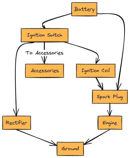
Ignition System
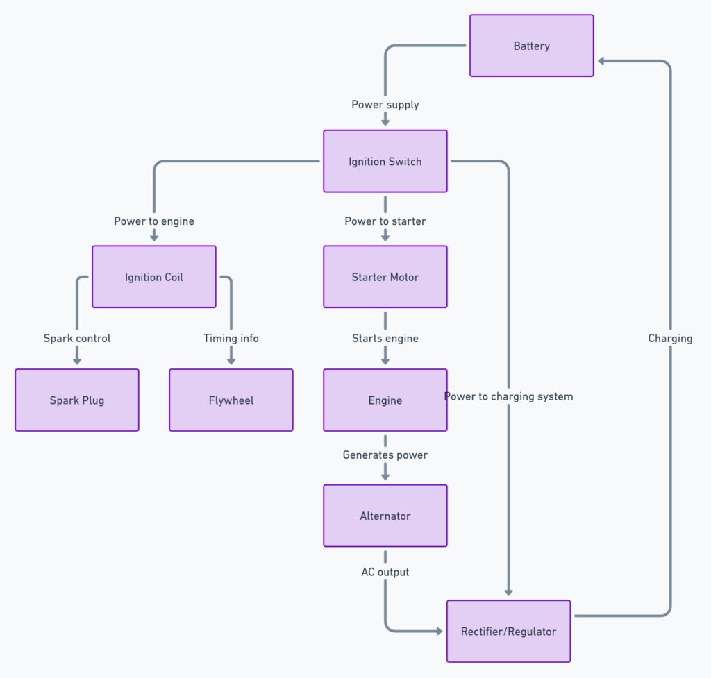
This includes the ignition coil, spark plug, rectifier, battery, and key switch wiring. Proper ignition system wiring is critical to engine operation.
Charging System
The charging system wiring consists of the alternator stator and regulator/rectifier. This keeps the battery charged when the engine is running.
Electric Starter
The wiring runs from the starter motor solenoid activated by the key switch to the starter motor itself. This engages the starter to crank the engine.
Engine Sensors
Wiring for critical engine sensors like the oil alert unit and throttle position sensor are shown. These provide key input signals to the engine control module.
Control Module Connections
The wire harness connections between sensors/systems and the engine control module are provided. The module coordinates ignition timing and air fuel mixture.
How to Read the GX390 Wiring Diagram
When looking at the Honda GX390 wiring diagram, it helps to recognize some basic symbols and conventions used in the diagram:
- Power wires are typically red or orange
- Ground wires are typically black
- Any green wires pertain to spark timing
- Connector pinouts show wire locations within a connector
- An arrow crossing wires indicates they are joined
Additionally:
- Follow current flow starting from the battery source
- Recognize splices connecting additional wires
- Note wire gauge – thicker lines carry more current
Having a wiring diagram legend that defines symbols and wire colors is also essential.
Final Thoughts on the Honda GX390 Wiring Diagram
The GX390 wiring diagram provides a thorough and comprehensive overview of all engine electrical components and wiring. Becoming familiar with its contents before working on the engine is critical.
Pay particular attention to:
- Wire routes between components
- Connector views defining pinouts
- Splice points with additional wires joining
- Wire gauges indicating capacity
Taking the time to correctly interpret the Honda GX390 wiring diagram will allow you to efficiently troubleshoot problems, trace electrical faults, and properly modify or install new components. Maintaining and updating any changes to the wiring is also essential.
Having the correct diagram for your specific GX390 engine is key – there may be minor variations between model years. Consult your diagram before attempting any troubleshooting or repairs.
