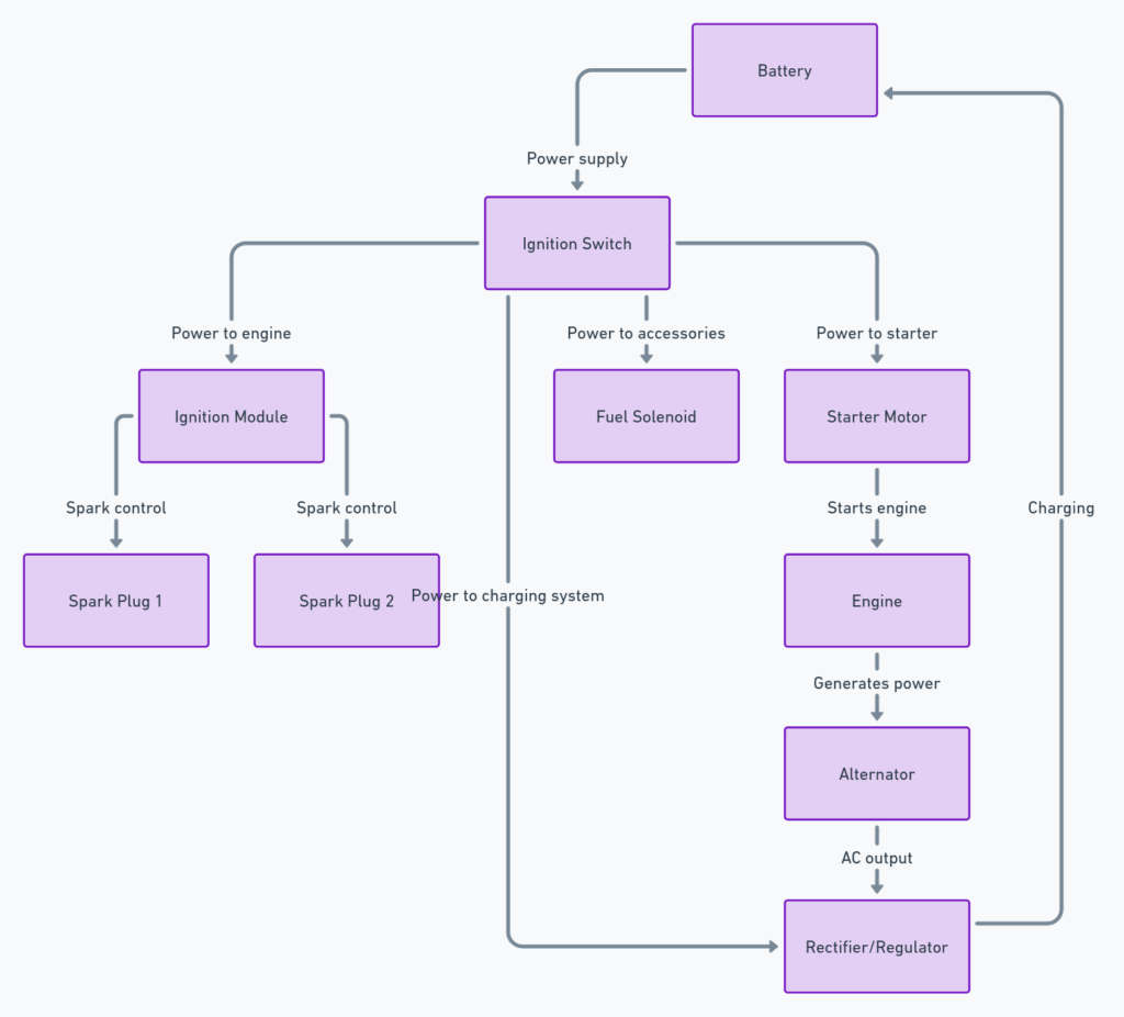
Honda GX630 Wiring Diagram
The Honda GX630 is a large 25.5 HP commercial grade V-twin engine often used in agricultural, construction, and industrial applications. Navigating the GX630 wiring diagram is critical when troubleshooting, repairing, or maintaining this engine. In this blog post, we’ll provide an overview of the GX630 wiring schematic and highlight some key components and connections.
Honda GX630 Wiring Diagrams
Diagram 1:

Diagram 2:

Diagram 3:

Diagram 4:

Diagram 5:

Contents of the GX630 Wiring Diagram
The GX630 wiring diagram includes the following elements:
Electrical Symbols
- Power sources, grounds, switches, relays, fuses
- Solenoids, sensors, battery, starter motor
- Wire connectors and splices
Wiring Colors
- Black: Ground wires
- Red: Main power wires
- White: Accessory power wires
- Green: Signal wires
Component Labels
- Starter motor, ignition coil, rectifier, CDI unit
- Oil pressure switch, fuel solenoid valve, throttle position sensor
How to Read the GX630 Wiring Diagram
When reading the GX630 wiring diagram, follow the path of the main red power wires from the battery source through various components. Branching white and green wires connect accessories and sensors to power or ground. Pay attention to connectors, splices, grounds, and interfaces between components. Follow the flow through the ignition, charging, and starting systems.
Power Sources
The battery provides 12V power to the starting and ignition systems. The alternator and rectifier produce 12V to power accessories and charge the battery when the engine is running.
Ground Points
Multiple ground points exist on the metal frame and engine block, all connected by black wires. Grounds complete the power flow in circuits.
Ignition System
The CDI ignition unit controls ignition coil signals. Wires lead from the coils to the spark plugs. An ignition switch and emergency stop switch circuit cuts power.
Charging System
The alternator charges the battery and powers accessories while the engine runs via the rectifier and main power wires.
Starting System
The starter motor circuit engages when the key switch is turned to START, sending current to the small wire on the solenoid which closes the main power contacts. Large power wires then send current from the battery to the starter motor.
Final Thoughts on the Honda GX630 Wiring Setup
The GX630 uses a sophisticated but straightforward automotive-style electrical system with a 12V battery, charging alternator, CDI electronic ignition, electric starter motor, sensors, and multiple control switches. By following the color coded wires in logical flows between components on the diagram, the connections can be clearly understood. Becoming familiar with this diagram is essential for successfully maintaining, troubleshooting, or repairing issues with the Honda GX630 engine. Reach out to a Honda technician for expert advice on tackling any electrical gremlins in the GX630 wiring harness.
