2-Way Switch Wiring Diagram
A 2-way switch is a type of electrical switch that allows you to control a light or other electrical device from two different locations. This is a common setup in homes and buildings, where you might want to be able to turn on a light from both the top and bottom of a staircase, for example. The 2-way switch wiring diagram is a visual representation of how these switches are connected, and understanding it is essential for anyone working on electrical projects.
What’s Included in a 2-Way Switch Wiring Diagram?
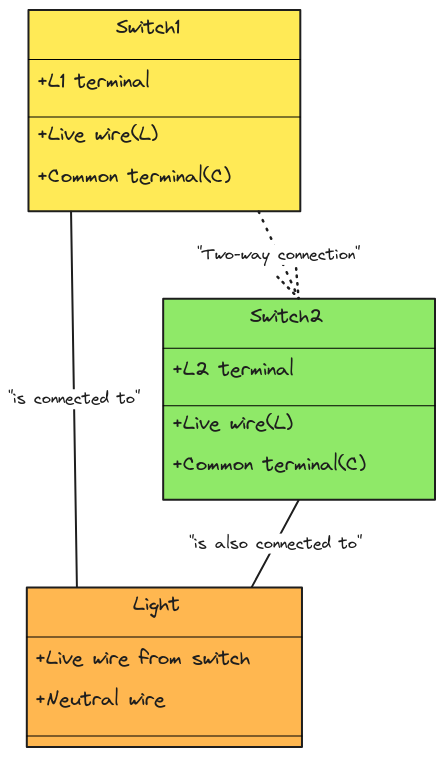
A 2-way switch wiring diagram typically includes the following components:
- Power source (usually the main electrical panel)
- 2-way switch
- Light fixture or other electrical load
- Connecting wires
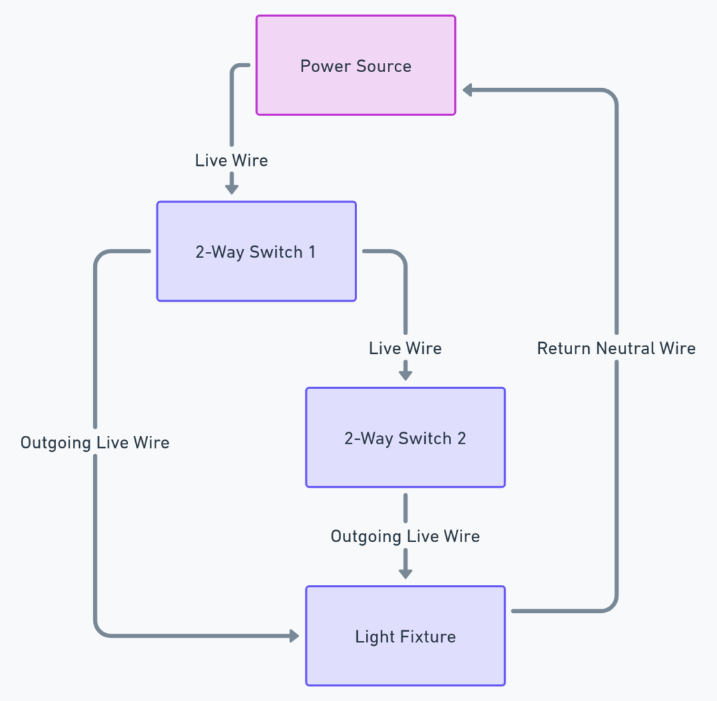
The diagram shows how these components are wired together to allow the light to be turned on and off from either switch location.
2-Way Switch Wiring Diagrams
Diagram 1:

Diagram 2:

Diagram 3:

Diagram 4:

How to Read a 2-Way Switch Wiring Diagram
Reading a 2-way switch wiring diagram is relatively straightforward. The power source is typically represented by a single line, while the 2-way switches and light fixture are shown as separate symbols. The connecting wires are represented by lines, and the direction of the current flow is usually indicated by arrows.
To understand how the system works, you can follow the flow of the electrical current from the power source, through the switches, and to the light fixture. When one switch is in the “on” position, it completes the circuit, allowing current to flow and the light to turn on. When the other switch is in the “on” position, it also completes the circuit, allowing the light to be turned on from the other location.
Common Wiring Configurations
While the basic 2-way switch wiring diagram remains the same, there are a few common variations that you might encounter:
- Wiring with a neutral wire: In some cases, a neutral wire may be included in the wiring diagram, providing an additional path for the electrical current to flow.
- Wiring with multiple lights: The 2-way switch wiring diagram can be used to control multiple lights from two different locations.
- Wiring with additional switches: In some cases, additional 3-way or 4-way switches may be incorporated into the wiring diagram to provide even more control over the lighting or other electrical devices.
Understanding the Electrical Principles
At the heart of a 2-way switch wiring diagram are the basic principles of electrical circuits. The switches are used to interrupt the flow of electrical current, allowing you to turn the light on and off from different locations. By understanding these principles, you can not only read and interpret the wiring diagram but also troubleshoot any issues that may arise with the electrical system.
Practical Applications
The 2-way switch wiring diagram is a valuable tool for anyone working on electrical projects, whether it’s a DIY home improvement task or a larger commercial or industrial project. By understanding how these switches work and how to read the wiring diagram, you can ensure that your electrical systems are properly installed and functioning correctly.
Conclusion
The 2-way switch wiring diagram is a essential tool for anyone working on electrical projects. By understanding the components included in the diagram, how to read it, and the underlying electrical principles, you can confidently tackle a wide range of electrical tasks and ensure that your systems are safe and effective. Whether you’re a homeowner, electrician, or someone just interested in learning more about electrical systems, this guide should provide you with the information you need to get started.


