6 Wire Thermostat Wiring Diagram
A 6 wire thermostat wiring diagram is a crucial tool for understanding and properly installing a thermostat in your home or office. This comprehensive guide will walk you through the key components of a 6 wire thermostat system, how to interpret the wiring diagram, and provide helpful tips for a successful installation.
What’s Included in a 6 Wire Thermostat Wiring Diagram?
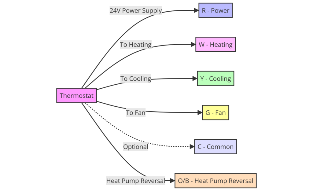
A 6 wire thermostat wiring diagram typically includes the following components:
- Power (R or Rc): This wire provides the necessary power to operate the thermostat.
- Common (C): The common wire completes the circuit and allows the thermostat to communicate with the HVAC system.
- Heat (W or Wh): The heat wire controls the heating function of the HVAC system.
- Cool (Y or Yc): The cool wire controls the cooling function of the HVAC system.
- Fan (G): The fan wire controls the operation of the HVAC system’s fan.
- Accessory (A or Aux): The accessory wire is used to control additional features, such as a humidifier or dehumidifier.
6 Wire Thermostat Wiring Diagrams
Diagram 1:

Diagram 2:

Diagram 3:

How to Read a 6 Wire Thermostat Wiring Diagram
Reading a 6 wire thermostat wiring diagram is straightforward. Each wire is labeled with a letter or abbreviation that represents its function. To properly connect the thermostat, you’ll need to match the wires from the thermostat to the corresponding wires in your HVAC system.
Common 6 Wire Thermostat Configurations
While the basic 6 wire thermostat wiring diagram remains the same, there can be variations in the specific configurations. Some common 6 wire thermostat configurations include:
- Conventional Heating and Cooling: This setup is the most common, with the power, common, heat, cool, fan, and accessory wires all connected.
- Heat Pump: In a heat pump system, the cool wire is often labeled as “compressor” and the accessory wire may be used for auxiliary heat.
- Dual-Fuel: Dual-fuel systems use both a furnace and a heat pump, requiring the use of the accessory wire for the auxiliary heat source.
Troubleshooting Common 6 Wire Thermostat Issues
If you encounter any issues with your 6 wire thermostat, here are some common troubleshooting steps:
- Verify Wiring Connections: Ensure that all wires are securely connected to the corresponding terminals on both the thermostat and the HVAC system.
- Check for Voltage: Use a multimeter to test for the presence of voltage on the power (R or Rc) and common (C) wires.
- Identify Faulty Components: If the thermostat is not functioning as expected, the issue may be with the thermostat itself or the HVAC system components.
Conclusion
A 6 wire thermostat wiring diagram is an essential tool for properly installing and maintaining a thermostat in your home or office. By understanding the components and how to read the diagram, you can confidently tackle any 6 wire thermostat project and ensure your HVAC system is functioning at its best.


