How to Test a Relay: Step-by-Step Guide for All Skill Levels

Relays are essential for controlling high-power devices through low-power signals across a wide range of electrical systems, from automotive and household appliances to industrial machinery. Testing relays ensures reliable performance and reduces the risk of electrical issues that could impact connected devices. This guide walks through various relay testing techniques, including multimeter testing, continuity checks, and detailed methods for both electromagnetic and solid-state relays.
What is a Relay?
A relay is an electrical switch that uses a small control signal to open or close a larger circuit. In essence, it allows a low-power input to control high-power operations. Relays are classified into several types based on their function and design:
- Electromagnetic Relays: These use magnetic force created by an energized coil to open or close a circuit.
- Solid State Relays (SSR): These are electronically operated and contain no moving parts.
- Automotive Relays: Specifically designed for vehicles, these relays manage systems like fuel pumps, lights, and ignition.
Testing a relay helps identify faults in these devices, maintaining system integrity and preventing unexpected shutdowns or malfunctions.
Preparing for Relay Testing: Tools and Safety
Tools Required for Testing a Relay
Before you start, gather the following tools:
- Multimeter: For resistance and continuity measurements.
- Test Light: To verify voltage and current flow in automotive applications.
- 12V or Specified Power Source: Used to activate the relay during testing.
Safety Precautions
Always follow these precautions to ensure safe testing:
- Disconnect the relay from the power source to avoid accidental shocks.
- Use insulated gloves if working on high-voltage relays.
- Double-check the relay’s specifications on the datasheet before applying power.
Step-by-Step Guide: How to Test an Electromagnetic Relay
Testing an electromagnetic relay involves checking its internal coil, normally closed (NC) and normally open (NO) terminals, and switch operation.
Step 1 – Locate and Identify Relay Terminals
Start by identifying the relay terminals, which are often labeled:
- Coil Terminals (usually labeled 85 and 86 in automotive relays)
- Common Terminal (COM)
- Normally Open Terminal (NO)
- Normally Closed Terminal (NC)
Consult the relay’s datasheet if you are unsure of the terminal layout.
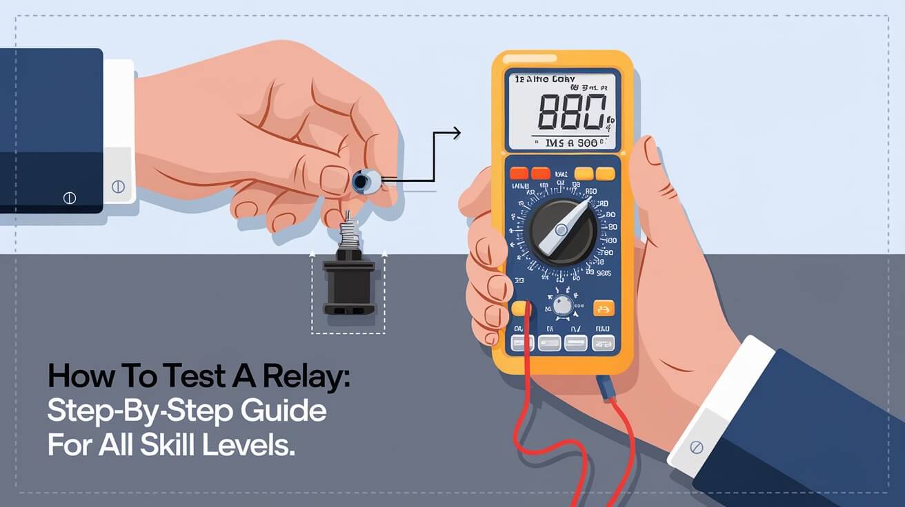
Step 2 – Testing Coil Resistance
- Set the multimeter to the resistance or ohms setting.
- Connect the multimeter probes to the coil terminals. Expected resistance values vary by relay but typically fall between 50 and 120 ohms.
- If the reading is significantly higher or lower than specified, it may indicate a faulty or damaged coil.
Step 3 – Checking Normally Closed (NC) and Normally Open (NO) Terminals
- With the relay de-energized, use the multimeter to check the NC and NO terminals.
- The NC terminal should show close to zero resistance, indicating continuity.
- The NO terminal should display an open circuit (infinite resistance) when the relay is not energized.
Step 4 – Energizing the Relay and Testing Switch Function
- Apply a suitable voltage to the relay’s coil terminals to activate it.
- You should hear a “click” as the internal switch operates.
- While energized, test the NO terminal. It should show continuity (zero resistance) if functioning correctly.
Step 5 – Testing Voltage on the Switched End
Set the multimeter to DC voltage mode and check the voltage across the switch terminals, which should match the expected power output specified by the relay.
Step-by-Step Guide: Testing a Solid State Relay (SSR)
Testing solid-state relays (SSRs) differs from electromagnetic ones, as SSRs lack physical contacts and rely on electronic components for switching.
Step 1 – Connecting the Control Voltage
- Connect a control voltage (e.g., 9V DC) to the input terminals to activate the SSR.
- Ensure the applied control voltage aligns with the relay specifications.
Step 2 – Testing Load Side with an AC Source
- Attach a load, such as a light bulb, to the SSR’s AC load terminals.
- When the control voltage is applied, the load should activate if the SSR is functioning.
Step 3 – Testing SSR in Diode Mode
- Set the multimeter to diode mode and measure the voltage drop across the input terminals.
- Compare the reading to the SSR specifications. A significant deviation may indicate a problem.
Additional Relay Testing Methods and Troubleshooting Tips
Visual Inspection and Physical Testing
Look for:
- Signs of Wear or Corrosion: These can affect contact and terminal functionality.
- Physical Damage: Cracked casings or burnt marks could signal serious faults.
Swapping Relays for Diagnosis
If possible, swap a suspect relay with a known working one to isolate the issue. If the circuit works with the replacement, the original relay likely has an internal fault.
Diagnosing Relay Malfunctions with Symptoms
Common relay issues include:
- Intermittent Clicking: Could indicate a failing coil or intermittent contact.
- Sticking Relays: Often caused by internal contact wear, sticking relays may require replacement.
- Erratic Switching: Potentially caused by coil degradation or dirty contacts.
Frequently Asked Questions (FAQs) on Relay Testing
What are the common signs of a faulty relay?
Faulty relays may cause intermittent circuit operation, fail to activate, or show abnormal resistance readings. Frequent “clicking” or physical wear can also indicate potential issues.
Can a relay be repaired, or should it be replaced if faulty?
While some relays can be disassembled for cleaning, most faults require replacement as internal components aren’t easily repairable.
How often should relays be tested?
Relays in critical systems should be tested annually, while others can be tested as part of routine equipment maintenance.
What is the difference between testing DC and AC relays?
AC relays may require different power sources or testing techniques, especially with SSRs, which may need specific voltage sources. Always refer to the datasheet for precise testing methods.
Conclusion
Testing relays is essential for ensuring reliable performance across automotive, household, and industrial applications. By using multimeters, continuity tests, and various diagnostic methods, you can accurately assess relay condition, prolong their life, and prevent unexpected failures. With regular testing, you’ll be better equipped to maintain the safety, efficiency, and durability of your electrical systems.


