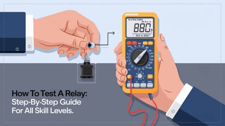
How to Check a Relay: Complete Guide to Diagnose and Test Relays

Relays are essential in many electrical and automotive systems, serving as switches that help control circuits by using low-power signals to manage higher-power loads. Over time, relays can wear out or fail, which can disrupt the proper functioning of connected systems. Testing a relay can help you quickly determine whether it’s functioning as it should or if it requires replacement. In this guide, we’ll walk you through the complete process of how to check a relay, from tools and preparation to advanced troubleshooting techniques.
Tools Needed for Relay Testing
Before you begin testing, gather the following tools:
- Multimeter: For measuring resistance, continuity, and voltage across relay contacts.
- Power Source: A 12V battery or benchtop power supply.
- Test Light: A simple light that confirms if power is present in certain relay points.
- Jumper Wires/Alligator Clips: For easy and stable connections.
Having these tools ready ensures a smooth process when testing the relay, allowing for accurate and consistent results.
Relay Basics: Components and Types
Relay Structure
Relays typically have a coil, common terminal (COM), normally open (NO) terminal, and a normally closed (NC) terminal. When the relay coil is powered, it acts like a switch, creating a connection between the NO and COM terminals.
Types of Relays
- Electromechanical Relays (EMR): Operate via an electromagnetic coil.
- Solid State Relays (SSR): Use semiconductor switches to operate, generally faster and more durable than EMRs.
- Automotive Relays: Commonly found in vehicles, usually in 4- or 5-pin configurations.
Different types of relays may require different testing methods, but basic tests often apply across the board.
How to Test an Electromechanical Relay
Identify and Label Pins
Each relay has specific pins: usually, 85 and 86 connect to the coil, and 30, 87, and 87a are for contacts. The coil powers the switch between these contacts, so understanding which pins serve which role is essential before beginning any tests.
Measure Coil Resistance
- Set your multimeter to measure resistance (ohms, represented by the symbol Ω).
- Place the probes on the coil terminals, usually marked 85 and 86.
- If the resistance falls between 50 and 200 ohms (values may vary with the relay type), the coil is functional. Low resistance indicates a short, while very high resistance could mean an open circuit.
Test Continuity on NC and NO Terminals
- NC Terminal: Place one probe on the COM terminal and the other on the NC terminal. A good NC terminal will show near-zero resistance when the relay is unpowered.
- NO Terminal: Place the probes on the COM and NO terminals. This should display high resistance when unpowered. If the relay is activated, continuity (near-zero resistance) should appear, signifying proper function.
Energize the Relay and Listen for the Click
- Connect a 12V power source to the coil terminals (85 and 86) to energize the relay.
- Listen for a click—this sound indicates that the relay coil has activated, causing internal switching.
- Observe the multimeter readings between NO and COM terminals to ensure near-zero resistance when energized.
If the relay clicks but doesn’t complete the connection, internal components may be faulty.
Check Continuity with an Energized Relay
After energizing, connect the probes between the NO and COM pins. When energized, the reading should confirm continuity. If you don’t see the expected change, the internal contacts may be damaged.
Testing Solid State Relays (SSR)
SSRs operate differently from mechanical relays and require specific testing techniques.
- Test DC-Controlled SSRs: Use a small load (like a light bulb) to check if the SSR switches correctly when control voltage is applied.
- Test AC-Controlled SSRs: Connect an appropriate AC load and check if the relay activates with control voltage.
- Use Diode Test Mode on Multimeter: For more advanced testing, the multimeter’s diode mode can check semiconductor integrity inside SSRs.
These methods apply differently based on the relay type, so refer to the datasheet for specifications.
Using a Multimeter to Test Different Aspects of a Relay
Resistance Testing
When testing coil resistance, set your multimeter to ohms and measure between the coil pins (85 and 86). If the resistance reading is within the range listed in the relay’s datasheet, the coil is functional.
Continuity Testing
When the relay is deactivated, there should be continuity between COM and NC pins, and an open circuit between COM and NO. When powered, continuity should switch to COM and NO.
Voltage Testing
After confirming continuity, measure voltage across contacts to ensure the relay supplies the correct output voltage. Insufficient voltage can indicate corrosion or wear on internal relay contacts.
Advanced Techniques for Relay Diagnostics
Swap Relays
Replacing the questionable relay with a known-working relay can quickly diagnose issues. Be cautious, as this may risk damaging a functioning relay if a circuit issue exists.
Circuit Connection Testing
Inspect and test the relay circuit for loose wires or connectors that may interfere with power delivery.
Check for Physical Damage
Burn marks or rust on relay pins can affect performance. Any sign of melting or physical degradation means the relay should be replaced immediately.
Troubleshooting Common Relay Problems
Relay Won’t Click or Activate
If there’s no sound upon energizing, the relay coil might have an open circuit or there may be an issue with the power source.
No Continuity on NO Terminal
If continuity fails to appear on the NO terminal, the contacts may be corroded or stuck in the open position.
Intermittent Relay Function
This can be due to weak coils or loose connections. Clean any contact points and check for stable, uninterrupted power to the relay.
How to Test Automotive Relays
Locating the Relay
Automotive relays are often found in fuse boxes under the hood or within the dashboard. Use the vehicle manual for specific locations if you’re unsure.
Simple Swap Test
A straightforward approach is to swap the suspected relay with a similar, functional one in the vehicle’s fuse box.
Powering the Coil with a Car Battery
Connect the relay to the car battery to energize it and check for activation. Ensure the battery provides steady 12V power to avoid false test results.
Common Automotive Relay Issues
Some issues specific to vehicles include faulty fuel pump relays, starter relays, and headlight relays. Each failure has unique symptoms, from flickering lights to failure to start, which make relay testing essential.
Safety Tips and Best Practices in Relay Testing
- Use the appropriate multimeter settings to avoid damage.
- Never exceed the relay’s voltage rating during testing.
- Ensure connections are secure, and avoid testing with wet or greasy hands.
Frequently Asked Questions
What are the signs of a bad relay?
Common signs include inconsistent or failed operation of devices connected to the relay, such as lights not turning on, starter not engaging, or equipment shutting off unexpectedly.
Can a damaged relay be fixed?
Typically, relays are replaced rather than repaired, as internal components are sealed and difficult to access.
How often should relays be tested?
Relays in high-usage applications (e.g., cars, industrial machines) should be tested annually, or whenever symptoms of failure appear.
Conclusion
Testing a relay is crucial for maintaining electrical systems in vehicles and other applications. By regularly checking the relay’s operation with simple tools like a multimeter, you can ensure that your systems function smoothly. Proper relay testing methods, combined with caution and care, allow you to identify failing relays before they cause greater damage.


