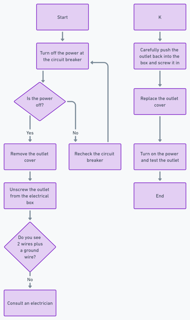
Basic Electrical Outlet Wiring Diagram
An electrical outlet wiring diagram is a visual representation of the internal connections and components within an electrical outlet. This diagram is essential for understanding the proper and safe installation of electrical outlets in your home or workspace. By comprehending the wiring diagram, you can ensure that your outlets are properly grounded, configured, and functioning correctly.
What’s Included in an Electrical Outlet Wiring Diagram?
A basic electrical outlet wiring diagram typically includes the following components:
- Hot/Live Wire (Black): This wire carries the electrical current from the electrical panel to the outlet.
- Neutral Wire (White): This wire completes the electrical circuit and returns the current to the electrical panel.
- Ground Wire (Green or Bare Copper): This wire provides a safe path for electrical current in the event of a fault, helping to prevent electrical shocks and fires.
- Outlet Receptacle: The physical outlet where you plug in your electrical devices.
Basic Electrical Outlet Wiring Diagrams
Diagram 1:

Diagram 2:

Diagram 3:

Diagram 4:

How to Read an Electrical Outlet Wiring Diagram
To read an electrical outlet wiring diagram, follow these steps:
- Identify the Hot/Live, Neutral, and Ground Wires: The hot/live wire is typically black, the neutral wire is white, and the ground wire is green or bare copper.
- Understand the Connections: The hot/live wire connects to the smaller slot on the outlet, the neutral wire connects to the larger slot, and the ground wire connects to the round hole or terminal.
- Visualize the Circuit: The hot/live wire carries the current from the electrical panel to the outlet, the neutral wire completes the circuit by returning the current to the panel, and the ground wire provides a safe path for any stray current.
Common Electrical Outlet Types
- Duplex Outlet: This is the most common type of electrical outlet, featuring two receptacles for plugging in devices.
- GFCI Outlet: Ground Fault Circuit Interrupter (GFCI) outlets are designed to protect against electrical shocks and are often found in bathrooms, kitchens, and outdoor areas.
- USB Outlet: These outlets feature built-in USB ports, allowing you to charge your electronic devices without the need for a separate adapter.
- Tamper-Resistant Outlet: These outlets have a built-in shutter system that prevents access to the live parts, making them safer for use around children.
Troubleshooting Common Electrical Outlet Issues
If you encounter any issues with your electrical outlets, such as not receiving power, tripped circuit breakers, or loose connections, it’s important to refer to the wiring diagram and follow proper safety protocols. In some cases, it may be necessary to consult with a licensed electrician for more complex repairs or modifications.
Conclusion
Understanding the basic electrical outlet wiring diagram is crucial for maintaining a safe and functional electrical system in your home or workspace. By being familiar with the components and connections, you can ensure that your outlets are properly installed, grounded, and operating as intended. Remember to always prioritize safety and consider consulting a professional electrician for any complex electrical work.


