Car Wiring Diagram: Complete Guide to Understanding
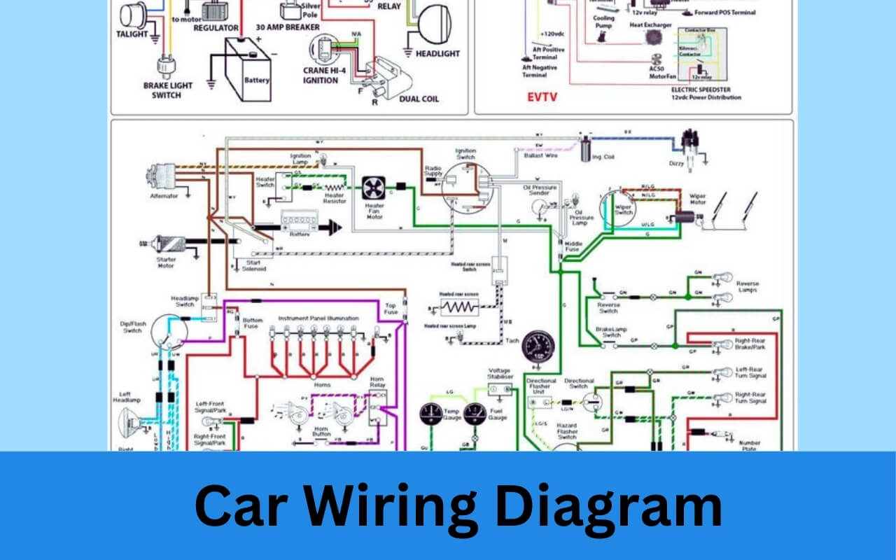
Have you ever opened the hood of your car, saw the spaghetti-bowl of wires and electrics, and wondered – “how do I make heads or tails of this?”
The answer lies in understanding automotive wiring diagrams. These schematics serve as roadmaps to systematically trace, diagnose, and repair electrical issues in vehicles.
In this comprehensive guide, you’ll learn exactly what wiring diagrams are, why they’re important, how to read them, where to access diagrams specific to your vehicle, and how technicians leverage them to fix problems.
We’ll demystify this crucial – yet often misunderstood – aspect of automotive repair and maintenance. So if you want to save money by doing your own basic electrical troubleshooting or just better understand your car, this is the guide for you!
What are Car Wiring Diagrams?
Wiring diagrams, sometimes referred to as wiring schematics or electrical diagrams, are technical drawings that document electrical systems and circuit connections in vehicles.
They utilize symbols and simplified representations of components to show how various lights, switches, sensors and other electrical components are wired together and interact within a particular system.
Think of an automotive wiring diagram like a roadmap. It allows both DIYers and professional technicians to trace the wiring through a vehicle to effectively identify and diagnose electrical issues and malfunctions.
These schematics highlight how power flows through relay and connection points between components – invaluable insight for anyone looking to test or repair their car’s electrical systems.
Why are Car Wiring Diagrams So Important for Auto Repair?
Wiring diagrams empower technicians to rapidly and reliably:
- Troubleshoot electrical issues
- Identify proper replacement parts
- Guide repair procedures
- Prevent critical mistakes
Without access to the technically precise diagram for your specific make, model, and year of vehicle, tracing wiring connections becomes extremely difficult and time consuming.
Misdiagnosing wiring issues can lead to introducing new problems by replacing the wrong parts or making incorrect connections.
Simplify diagnosing electrical faults by providing a detailed map specialized to your vehicle highlighting exactly how components connect.
Think of how maps make navigating unfamiliar cities easier – wiring diagrams serve the same purpose for navigating the complex electrical of modern automobiles.
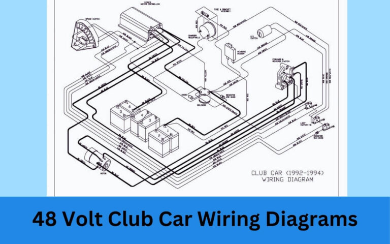
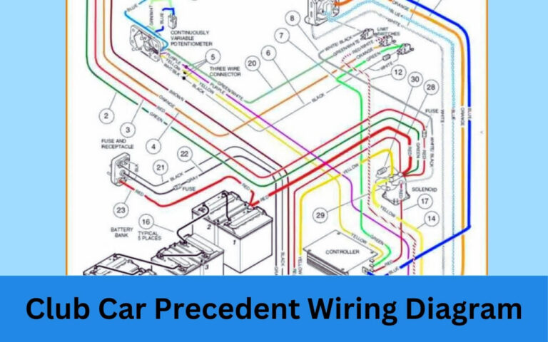
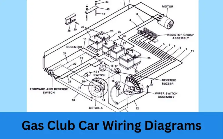
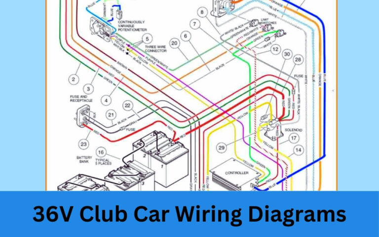
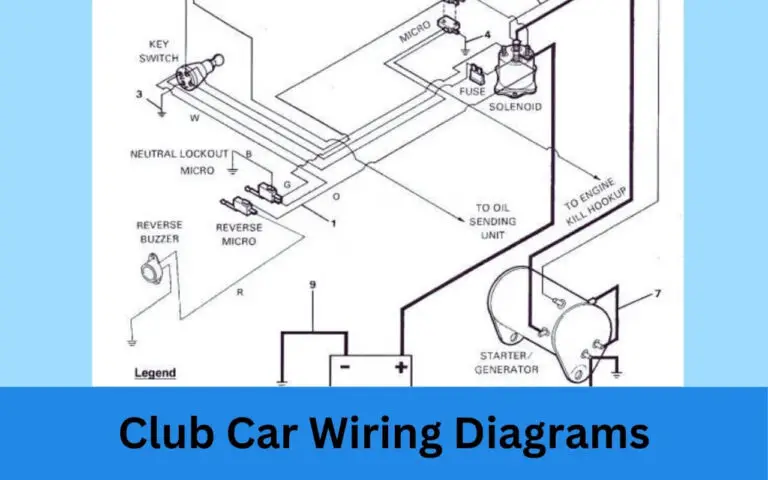
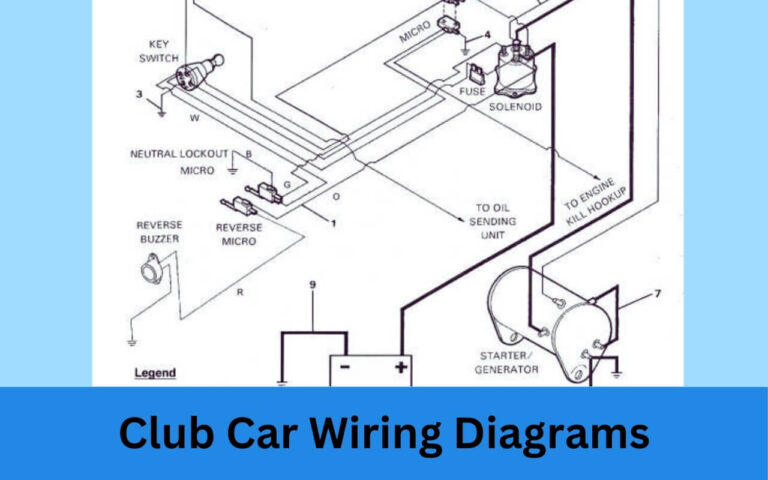
Car Wiring Diagrams
Diagram 1:
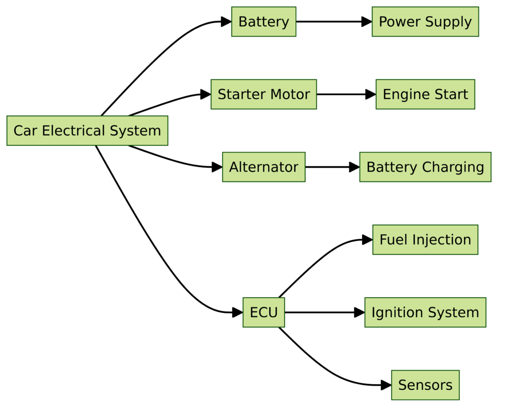
Diagram 2:

Diagram 3:

Diagram 4:
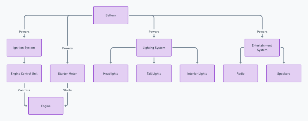
How to Read & Understand Car Wiring Diagrams?
While diagrams look complicated at first glance, understanding a few basic symbols and conventions will have you navigating your vehicle’s electrical system like a pro.
Let’s walk through some key components that will aid your understanding.
1. Recognize Common Symbols
Every electrical component found in a car has a corresponding symbol – the key to diagram comprehension. Here are a few common symbols you’ll encounter:
- Fuses – Protect circuits by sacrificing themselves before wires overheat
- Grounds – Provide return path for current to flow
- Resistors – Limit current flow
- Wires – Carry power through circuits
- Switches – Open or close circuits
- Relays – Use small current to control higher powered component
- Lights – Illuminate when powered
- Connectors – Join wires or components together
And many more representing stereos, coils, fuses, filters, and additional electronics. Consult diagrams key to identify unique symbols before tracing circuits.
2. Understand Color Coding
While not universally consistent, color codes give clues into circuit function.
Common standardized codes:
- Red – Power feeds
- Black – Ground wires
- Blue – Control circuits
- Yellow – Airbag systems
- Green – Data lines
Colors help techs quickly identify specific wires without needing to trace entire length.
3. Identify Systems
Component and wire labeling on diagrams match labels physically printed on devices and wires in your actual car.
So a wire labeled “Battery” on diagram connects to the positive or negative battery terminal. Labels like “Ignition System” or “Door Locks” clearly define what system a circuit belongs to.
Matching wiring diagram labels to physical components and wires simplifies troubleshooting. You know exactly what system a suspected fault belongs to.
4. Connect Numbers To Locations
Numbers next to components on diagrams correspond with locations shown on other sheets. So R13W/21 connects to a relay documented on page 21. Page 21 provides specifications on the relay itself and exact vehicle location.
Numbers match associated diagrams with detailed schematics by location – hugely helpful identifying replacement parts and access points.
With an understanding of key conventions used in diagrams, you can now leverage them to troubleshoot issues plaguing your vehicle!
Where To Find The Correct Wiring Diagram?
Accurately diagnosing electrical faults requires the perfectly matched diagram detailing specifics for your vehicle’s make, model, year, trim package, and options.
Here are the best resources to locate the ideal wiring diagram:
Vehicle-Specific Diagram Manuals
The most consistently reliable option comes from printed diagram compilation manuals from publishers like:
- Haynes – Contains simple diagrams and wiring locations
- Chilton’s – Comprehensive diagrams and repair procedures
Content organized by make, model, and year, often with trim specifics like engine options. Diagrams tailored exactly to your car reduces guessing which wires connect where.
Also highlight component locations under hood, interior dash, or throughout chassis – extremely helpful guiding repairs. If working on your car’s electrical system, these manuals are must-have tools.
Online Wiring Diagram Databases
If the upfront cost of printed manuals is prohibitive, check out online diagram databases:
- ALLDATAdiy – Enthusiast focused with convenient navigation
- Mitchell1 – Specifically designed for technicians
- AutoZone – Free resource with limited diagrams
Rendered electronically make searching simple by year and model – scroll and zoom to instantly highlight components and clearly trace wiring using color-coding and symbols.
Downside is paying monthly/yearly subscription for frequently updated, reliable diagrams. But for regular DIY use still more affordable long-run over time versus one-off manual purchases.
Manufacturer Service Manuals
Automaker factory repair documentation includes associated wiring diagrams:
- GM Service Information (GMSi)
- Ford Motor Company (FMC)
- Chrysler – Tech Authority
However access is expensive, aimed at dealer technicians with difficult off-board navigation of complex diagrams broken into hundreds of illustrations.
Consider as last resort accessing OEM guides. Great for vehicle-specific quirks not documented aftermarket, but cumbersome compared to alternatives. VIN required.
Key Takeaway
No universal central database exists consolidating all OEM car wiring diagrams. But following the sources above gets you what you need through either print manuals or electronic subscriptions.
Focus your search by adding make/model/year + “wiring diagram” to locate vehicle-specific guides. The more tailored, the better accuracy tracing electrical gremlins!
How Do Mechanics Use Wiring Diagrams?
Professional technicians leverage wiring diagrams constantly throughout their diagnostic and repair process.
Serve as the main “road map” reference during troubleshooting by revealing connections between components that may seem entirely unrelated at first glance.
Here are just a few of the ways mechanics employ wiring diagrams:
1. Systematically Trace Symptoms
A “no start” condition for example could originate from faulty components like:
- Starter motor
- Battery
- Alternator
- Sensors
- Ignition switch
- And many more
Rather than replacing everything, wiring diagrams enable techs to logically test circuits step-by-step diagnosing the root cause of problems.
2. Identify Replacement Parts
Electrical issues often require component replacement – accurate diagrams pinpoint exactly which parts need installing by manufacturer part numbers.
Say a headlight suddenly stops working. Diagrams detail exactly which bulb, connector, fuse, relay, and wires run power to that light assembly – no guessing replacing random parts hoping to get lucky.
3. Guide Repair Procedures
Clear diagrams provide critical reference mapping complex wiring pathways. Especially important on extensive repairs like:
- Stereo installation
- Restoring corroded harness connectors
- Engine wire harness replacement
They reduce risk of accidentally disconnecting other circuits while working.
4. Prevent Costly Errors
Automotive wiring presents a delicate balance of power loads and voltage drops across connections.
One wrong pinched wire or disconnected ground can easily introduce electrical gremlins elsewhere.
Diagrams help techs ensure proper load balancing and routing during repairs to avoid unintended problems – saving comeback headaches down the road.
In summary – wiring diagrams serve as onboard GPS navigation systems when diagnosing and servicing electrical issues.
Key Takeaways – Car Wiring Diagrams
Still feel overwhelmed about the idea of tackling your own automotive electrical problems?
Here are the core concepts to remember:
- Wiring diagrams are simplified schematics tracing electrical connections.
- Recognize common symbols – fuses, grounds, resistors.
- Color codes help identify certain wires and systems.
- Use diagrams to systematically trace issues step-by-step.
- Purchase vehicle-specific manuals for accurate diagrams.
- They prevent mistakes and provide repair reference.
While gaining competency reading car wiring diagrams takes practice and experience, don’t be intimidated.
Even familiarizing yourself with the basics opens up huge potential tackling your own basic electrical issues – saving time and money down the road.
Hopefully this comprehensive guide has helped demystified vehicle wiring diagrams and empowered you to dig into that spaghetti bowl under the hood! Stay tuned for more technical automotive articles to come.

