Demystifying Chinese ATV 5 Pin CDI Wiring Diagrams
Have you ever stared confused at the rat’s nest of wires sprouting from your Chinese ATV, dirt bike, or go-kart engine? Do terms like CDI box, stator, ignition coil, and rectifier make your head spin when your ride suddenly sputters out on the trail? You’re not alone! Plenty of enthusiasts end up perplexed when dealing with electrical gremlins.
The good news is that the 5 pin CDI ignition setup found on most Chinese powersports vehicles is actually quite simple to understand and get back up and running if issues arise. Read on and I’ll walk you through everything you need to know, from identifying which wires do what, to troubleshooting no start conditions or weak spark situations. You’ll be back riding your 110cc or 150cc Chinese ATV, pit bike, and mini bike in no time.
We’ll cover:
- How the 5 pin CDI system works and why it’s commonly used
- What each wire in the CDI box does
- How to test the wires and system components
- Troubleshooting ignition problems
- Ignition coil and spark plug diagnosis
- Stator and rectifier replacement
- Helpful wiring diagrams and ignition theory
And plenty more! Buckle up and let’s get electrifying.
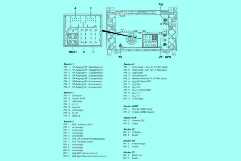
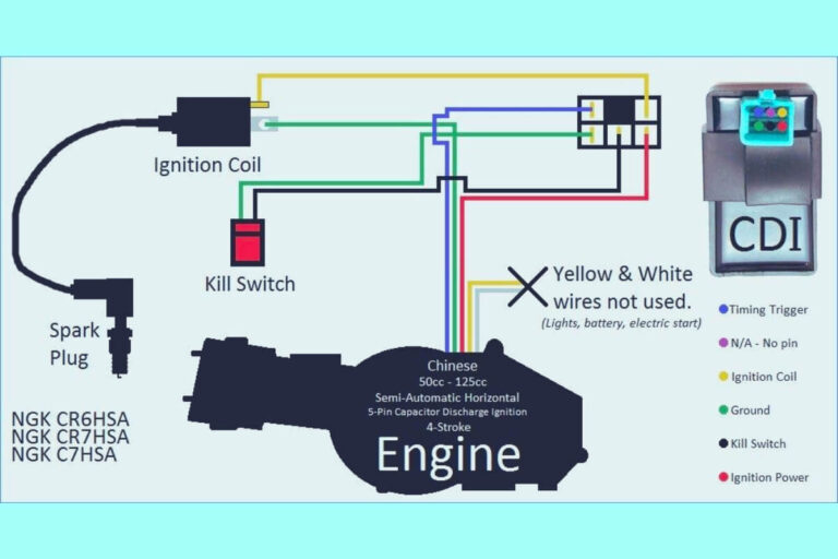
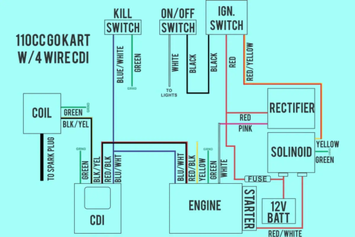
Chinese 5 Pin CDI Wiring Diagrams
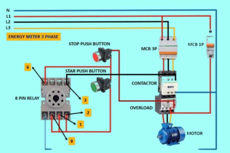
Diagram 1:
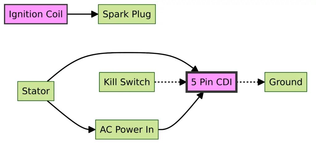
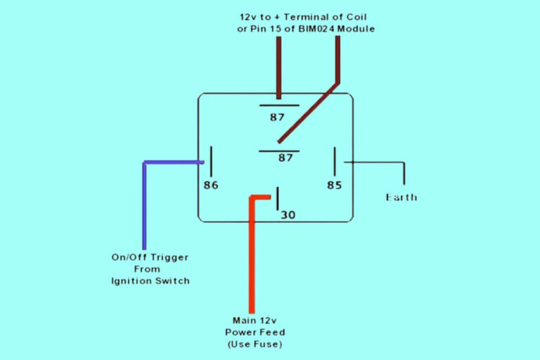
Diagram 2:

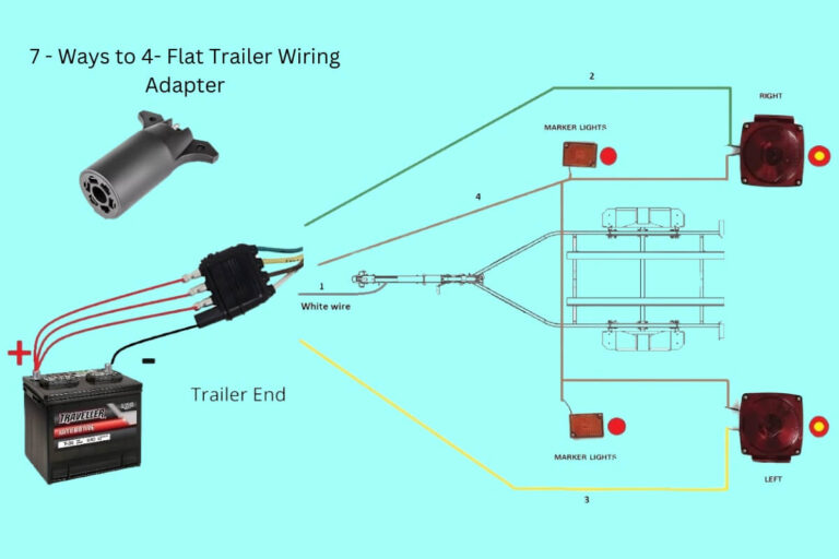
Diagram 3:

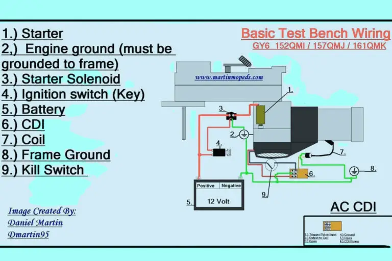
Diagram 4:

An Introduction to the 5 Wire Chinese CDI Ignition System
CDI stands for “Capacitive Discharge Ignition” and refers to the primary type of ignition system used on small Chinese engines, ranging from ATVs to dirt bikes, go karts, and other vehicles. This simple and cost-effective system is engineered to control the engine’s high voltage spark output through electrical component manipulation.
The 5 wires from the CDI unit connect to key components like:
- Ignition coil
- Power generation coils (the stator)
- Rectifier
- Battery
By switching ignition current on and off via this wiring network, the CDI box can “charge up” and send timed high voltage pulses to the spark plug.
Let’s breakdown each CDI wire in detail:
CDI Box Wire #1: AC Generator
The first CDI wire connects to power generation coils in the stator, also called the AC generator, flywheel magneto, or charging coils. Typically a single wire or pair of wires will run directly from the CDI box to the engine’s left crankcase where the stator lives around the flywheel.
This wire allows the CDI to pull information from the stator and time high voltage pulses correctly based on engine position.
CDI Wire #2: Ignition Coil Ground
The second wire provides a ground connection from the CDI unit directly to the ignition coil ground. Paired with wire #3, this creates the main ignition circuit that triggers combustion in the engine cylinders.
CDI Box Wire #3: Ignition Coil
Speaking of ignition coils, the third CDI wire runs to the negative lead of coil itself. Typically a single wire affair, when the CDI unit detects the signal from the flywheel stator that the piston is approaching top dead center compression stroke, it grounds this wire, allowing 120+ volts of electricity to jump from the coil’s secondary winding through to the spark plug tip.
CDI Wire #4: Stator Ground
On some setups a separate ground wire is dedicated to the stator coils and attached to the engine block. This stabilizes the ground connection from the stator and protects this sensitive electrical generator component.
CDI Box Wire #5: Battery Positive Voltage
Last but not least, to operate the switching action within the CDI box and ignition coil requires battery power, fed through the fifth CDI wire which leads to the positive terminal on the battery. This initiates current flow into the coil’s primary winding.
OK, now that we know which wires do what in a 5 wire CDI system, let’s talk about how we can test them.
Step-by-Step Guide to Testing CDI Box Wires
While Chinese engine electronics might look like a pile of tangled spaghetti upon first glance, diagnosing even the most ratty wiring job just takes some basic mechanical know-how and a multimeter capable of testing ohms, voltage, and continuity.
Here’s how to test each of the 5 CDI wires:
Checking Resistance on CDI Wires
First we’ll zero out the meter and make sure it’s set to resistance or continuity checking, signified by the Ω Ohms symbol. Then:
CDI Wire #1 and #4 – Stator Wires
Check that resistance does not exceed 1 Ohm through these wires. If you see significantly more, that means the stator windings have likely failed.
CDI Wire #2 and #3 – Ignition Coil Wires
You should read between 1.4 to 5 Ohms of resistance through these two CDI box wires that connect to the ignition coil. Out of spec means replace the coil.
CDI Wire #5 – Battery Voltage
Verify this last thick wire back to the battery shows continuity.
Next we’ll perform voltage checks:
Measuring Voltage at the CDI Box
Voltage testing pins down if electricity is actually making it from point A to B. Set your multimeter to voltage mode, then probe:
CDI Wires #1 and #4 – Stator Wires
Crank the engine while monitoring voltage – these wires should show 14+ Volts AC at high RPM which drops off when engine speed decreases. No voltage means stator failure.
CDI Wires #2 and #3 – Ignition Coil Wires
Voltage here should rapidly cycle while cranking the engine as the CDI unit creates on/off pulses as it operates the ignition coil. Constant 14+ volts would signify a CDI grounding issue.
CDI Wire #5 – Battery Voltage
This wire should always show 13+ Volts DC with key ON whether engine is cranking or not.
Use this testing data to zero in on bum CDI box components. If the wires check out, move upstream to troubleshoot.
Chasing Common Chinese ATV/Dirt Bike 5 Pin CDI Problems
So we’ve covered how CDI systems work on a high level and what functions all those wires serve. Now let’s tackle chasing down problematic gremlins like no start conditions through some informed troubleshooting tips.
Nothing kills the thrill quite like turning the key on your Chinese ride and instead of throaty combustion welcoming a silent, sad starter motor and no hope.
9 times out of 10, ignition issues come down to these key items:
Scenario 1: No Spark When Kicking Over
First, verify the kill switch is set to RUN vs STOP and that the engine stop switch wires are not faulty.
Assuming you’ve checked fuses and battery voltage (>12 volts), focus attention on the ignition coil and spark plug.
Remove the spark plug and insert it back into the plug cap. Then turn over the engine while grounding the threads of the plug and checking for bright, snappy spark discharge across the electrode.
- No spark means the coil is likely bad – replace it.
- Weak spark points to low battery voltage or faulty CDI unit – charge or replace.
- Solid spark but still no start indicates fuel delivery problems – inspect the carb.
Problem #2: Weak Spark When Hot
Overheating can cause ignition coils or stators to fail intermittently which leads to weak spark. Allow components to fully cool off. Then perform resistance checks using a multimeter on the ignition coil and stator as highlighted previously.
Out of spec? You’ve found the culprit!
Issue #3: Misfiring Under Acceleration
Here the coil or spark plug end up overwhelmed trying to ignite the air/fuel mixture.
- Try less aggressive break-in of a new engine
- Replace the spark plug
- Inspect coil windings for any cracked insulation and swap it out if needed
Problem #4: Sudden Loss of Power
Lastly – a sudden power drop generally relates to stator or CDI failure. Use a voltmeter to diagnose.
- Check stator resistance – should be under 1 Ohm
- Ensure >14V AC while running at the stator wires
- Measure battery DC voltage at the CDI wire
Zero in on the wires showing issues to track down the specific failed part rapidly.
Let’s continue and go into more detail on ignition coil and spark plug diagnosis since problems here can caused all sorts of difficult to diagnose hard starting and loss of power gremlins with Chinese powersports engines.
Step-by-Step Ignition Coil and Spark Plug Testing
The ignition coil transforms low voltage current into thousands of volts to jump the electrode gap on the spark plug and ignite compressed atomized fuel in the cylinder.
Here’s how to test both these components:
Checking Ignition Coil Resistance
Step 1: Remove the coil from the vehicle
Step 2: Set multimeter to Ohms mode Step 3: Touch the positive and negative meter leads to the coil’s primary terminals Step 4: Check meter readout – should be 1.1 to 1.6 Ohm on most Chinese bikes.
While a meter check verifies winding integrity, it takes a known good coil swapped in to conclusively pin a faulty one.
Spark plug testing follows a similar methodology:
Diagnosing Bad Spark Plugs
Step 1: Extract the plug
Step 2: Visually inspect for abnormal wear/deposits indicating running issues
Step 3: Use wire brush/sandpaper to clean the electrode
Step 4: Air gap should be 0.6 to 0.8mm – adjust as needed Step 5: Attach Ohm meter leads to the plug terminal and ceramic insulator
Step 6: Check meter readout – properly functioning plugs show 5,000+ Ohm
Step 7: Reinstall and test operation
coils and plugs wear over time. So even without obvious symptoms, replacing them every few years keeps things fresh.
Now let’s look at troubleshooting the power generation side of CDI ignition – the stator and rectifier charging components.
Testing Stators and Rectifiers
On the left side engine cover you’ll find three key power components:
- The pulsing stator which sends timing signals to the CDI box
- Lighting coils that charge the battery
- AC to DC rectifier that converts current
Here’s how to test both these circuits:
Checking Stator Resistance
Step 1: Unplug the stator connectors
Step 2: Remove the left engine cover Step 3: Disconnect the stator wires from the harness Step 4: Set multimeter to Ohms mode
Step 5: Test resistance across each stator lead
Readings vary widely by specific model and spec, but 1 Ohm or less generally indicates a healthy stator.
Rectifiers convert AC from the stator to 12V DC the battery needs. Failure causes low voltage.
Rectifier Testing
Step 1: Unplug the rectifier electrical connectors Step 2: Set your multimeter to diode checking mode Step 3: Touch the red voltmeter lead to each rectifier wire in sequence, then touch the black lead to to the other wires in turn.
Step 4: The working junctions should show 0.500+ voltage drop
With these tips you’ll be well-equipped to keep your Chinese engine’s CDI ignition running smoothly for years to come!
Key Takeaways on Diagnosing Chinese CDI Wiring and Ignition Systems
Let’s recap troubleshooting quick wins:
- Check for spark first if the engine won’t start
- Use resistance mode on a multimeter to test stator, CDI, and coils
- Look for 14V+ AC at stator wires while running
- Inspect spark plug condition for fouling/electrode gap
- Voltage drop outs point to bum rectifiers
- Test and replace ignition coils if spark weakens over time
Cracking the electrical gremlin code on a Chinese ATV, go kart, or other vehicle may seem intimidating but armed with this advice you’ll be back up and riding in no time.
Thanks for tuning in! While we’ve covered CDI ignition extensively, let me know in the comments if you have any other engine wiring questions. Whatever the issue, I’m confident we can get you sorted out. Ride on friends!

