Color Coded Wire Nest Thermostat Wiring Diagram
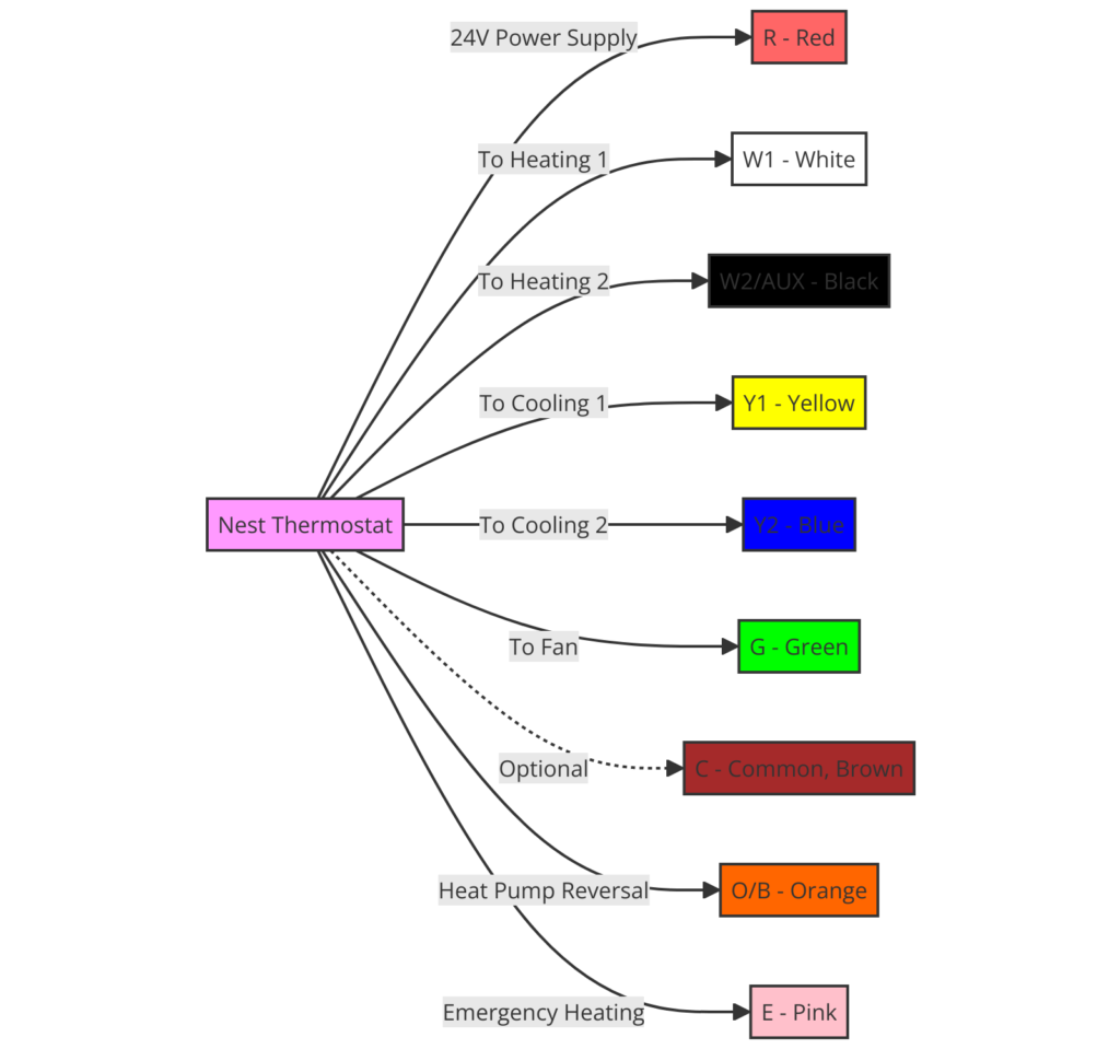
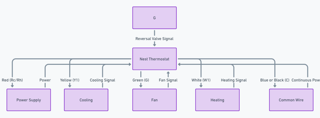
The color-coded wire nest thermostat wiring diagram is a crucial tool for homeowners and HVAC technicians when it comes to properly installing and maintaining a thermostat. This diagram provides a visual representation of how the various wires should be connected to ensure the proper functioning of the thermostat and the heating, ventilation, and air conditioning (HVAC) system.
What’s Included in the Diagram?
The color-coded wire nest thermostat wiring diagram typically includes the following key components:
- Terminal labels (C, W, R, G, Y, etc.) that correspond to the different wires and their functions
- Color-coded wires (e.g., red, white, green, yellow) that represent the different circuits within the HVAC system
- Connections between the thermostat and the various components of the HVAC system, such as the furnace, air conditioner, and fan
Color Coded Wire Nest Thermostat Wiring Diagrams
Diagram 1:

Diagram 2:

Diagram 3:

How to Read the Diagram
Reading the color-coded wire nest thermostat wiring diagram is straightforward, but it’s important to understand the purpose of each wire and terminal. Here’s a step-by-step guide:
- Identify the terminal labels: The diagram will typically show the different terminal labels (C, W, R, G, Y, etc.) that correspond to the wires.
- Match the wire colors: Look for the color-coded wires and match them to the appropriate terminal labels.
- Understand the wire functions: Each wire color represents a specific function within the HVAC system, such as the common wire (C), the heat wire (W), the power wire (R), the fan wire (G), and the cooling wire (Y).
- Follow the connections: Trace the connections between the thermostat and the various HVAC components to ensure that the wiring is correct.
Preparing the Wiring
Before attempting to connect the wires, it’s essential to turn off the power to the HVAC system. This is a crucial safety step to prevent any electrical hazards.
Once the power is turned off, you can begin the wiring process by following the color-coded wire nest thermostat wiring diagram. Ensure that each wire is securely connected to the appropriate terminal, and double-check your work to avoid any mistakes.
Troubleshooting Common Issues
If you encounter any issues with the thermostat or the HVAC system after installing the wiring, refer back to the color-coded wire nest thermostat wiring diagram. Common problems may include:
- The thermostat not responding or not turning on the HVAC system
- The HVAC system not functioning correctly (e.g., not heating or cooling properly)
- Incorrect wire connections or missing wires
By carefully reviewing the diagram and verifying the wire connections, you can often identify and resolve these issues.
Conclusion
The color-coded wire nest thermostat wiring diagram is a valuable tool for ensuring the proper installation and maintenance of your home’s HVAC system. By understanding the diagram and following the wiring instructions, you can ensure that your thermostat and HVAC system are functioning correctly and efficiently.


