CRX Climate Control Wiring Diagram
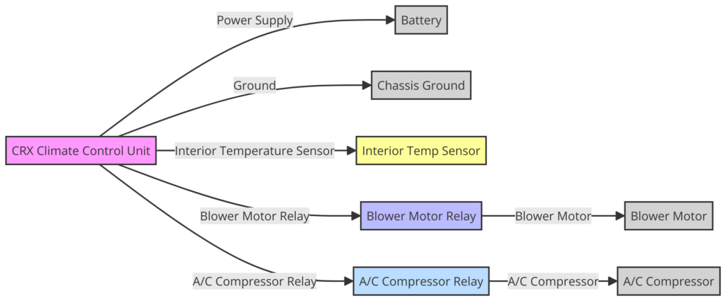
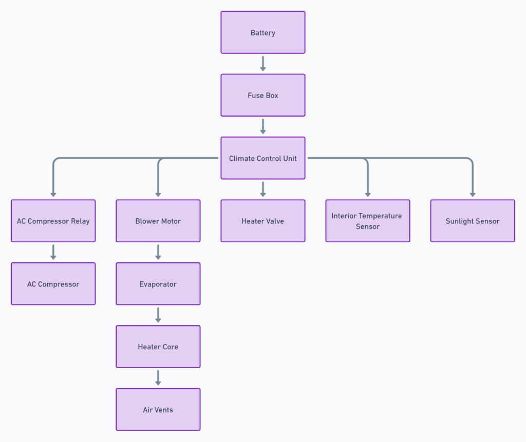
The climate control wiring diagram is a crucial resource for understanding and troubleshooting the intricate electrical system responsible for regulating the temperature and airflow inside your Honda CRX. This comprehensive blueprint unravels the complex web of connections, empowering you to navigate the inner workings of your vehicle’s climate control system with confidence.
What’s Included in the Diagram?
The CRX climate control wiring diagram typically encompasses the following components:
- Climate control unit
- Blower motor
- Blower motor resistor
- Temperature sensors
- Relays
- Fuses
- Wiring harnesses and connectors
CRX Climate Control Wiring Diagrams
Diagram 1:

Diagram 2:

Diagram 3:

How to Read the Diagram
At first glance, the climate control wiring diagram may appear daunting, but with the right approach, it can be deciphered with ease. Here’s how to navigate this intricate roadmap:
- Identify the Components: Familiarize yourself with the legend or key, which typically outlines the symbols used to represent each component in the diagram.
- Trace the Connections: Follow the wiring paths, paying close attention to the colored lines and their associated labels or numbers. These will guide you through the interconnections between various components.
- Cross-Reference: Refer to the accompanying text or notes, which often provide valuable insights into the diagram’s nuances, such as wire gauge specifications or grounding points.
Understanding the Climate Control Unit
The climate control unit acts as the brain of the system, receiving input from various sensors and user controls while coordinating the operation of the blower motor, air distribution, and temperature regulation. Examining the wiring connections to and from this central component is crucial for diagnosing and resolving climate control issues.
Blower Motor and Resistor Circuitry
The blower motor is responsible for circulating air throughout the cabin, and its performance is regulated by the blower motor resistor. The wiring diagram will illustrate the electrical pathways between these components, enabling you to troubleshoot issues related to improper airflow or fan speeds.
Temperature Sensor Integration
Temperature sensors play a vital role in maintaining the desired cabin temperature. The wiring diagram will highlight the connections between these sensors and the climate control unit, aiding in the identification of faulty sensors or wiring issues that may lead to temperature regulation problems.
Relay and Fuse Locations
Relays and fuses act as gatekeepers, controlling the flow of power to various components within the climate control system. The wiring diagram will pinpoint the locations of these critical components, facilitating efficient diagnosis and maintenance.
Wiring Harnesses and Connectors
Wiring harnesses and connectors are the arteries that carry the electrical signals throughout the system. The diagram will depict these pathways, enabling you to identify potential breaks, corrosion, or loose connections that may disrupt the climate control system’s operation.
Troubleshooting with the Wiring Diagram
Armed with a comprehensive understanding of the CRX climate control wiring diagram, you’ll be better equipped to tackle a wide range of issues. Whether you’re investigating a non-functioning blower motor, erratic temperature fluctuations, or intermittent system failures, the diagram will serve as your trusty guide, illuminating the intricate connections and potential problem areas.
Remember, while the wiring diagram is an invaluable resource, it’s always recommended to consult professional assistance for complex repairs or modifications to ensure the safety and longevity of your vehicle’s electrical systems.
