Delco Chevy 4 Wire Alternator Wiring Diagram
The Delco 4 wire alternator has been used by GM in their vehicles since the early 1970s and is still utilized today in certain models. This specific alternator configuration contains the following wires:
- Battery Cable
- Alternator Field Voltage Sense Wire
- Tachometer Signal Wire
- Voltage Regulator Wire
Compared to more modern 3 wire configurations, the Delco 4 wire utilizes an extra connection called a voltage regulator wire which connects to the voltage regulator.
Understanding the purpose and wiring of each terminal/wire is critical to properly installing and operating the alternator.
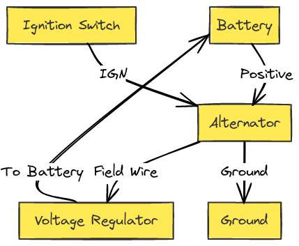
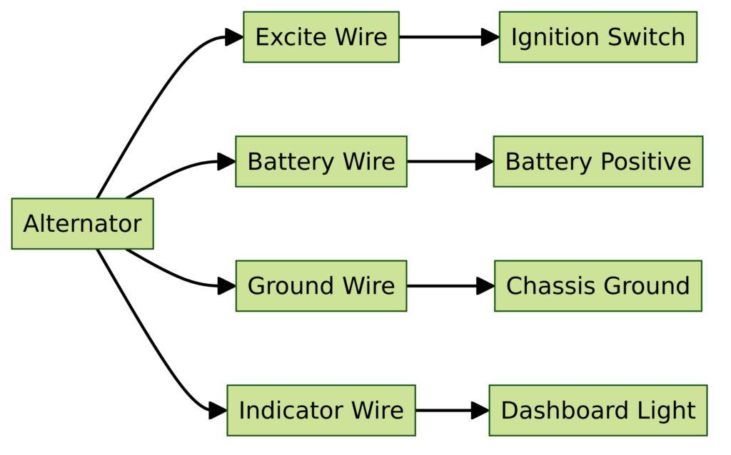
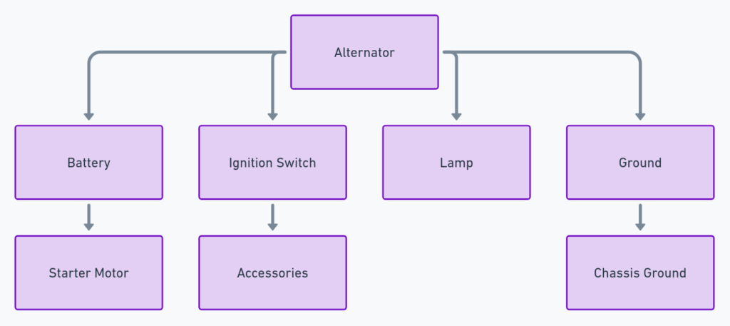
Delco Chevy 4 Wire Alternator Wiring Diagrams
Diagram 1:

Diagram 2:

Diagram 3:

Diagram 4:

Diagram 5:

Overview of the Key Terminals & Wires
Battery Cable – The battery cable provides positive current flow into the alternator which allows it to charge. This heavy gauge wire is typically terminated directly to the output B+ terminal on the back of the alternator.
Field Voltage Sense Wire – The field voltage wire connects internally to the voltage regulator and is used to monitor voltage at the battery to control alternator field current and output.
Tachometer Signal Wire – As its name implies, the tach signal wire provides a signal to the tachometer indicating engine RPM speed. This allows the gauge to display the operating speed of the motor.
Voltage Regulator Wire – This wire connects from the voltage regulator relay or module that acts to stabilize maximum charging voltage acting back to the voltage regulator internal to the alternator.
Reading The Delco Chevy 4 Wire Diagram
Let’s take a look at some example wiring diagrams to clarify connections to the Delco 4 wire alternator. We’ll include diagrams for more popular Chevrolet vehicles:
1970s & 80s GM Trucks With External VR
This diagram shows the typical alternator connections to the battery, warning lamp, voltage regulator (VR) and idiot light. Key points:
- External Voltage Regulator (VR) box is used mounted on the fenderwell
- The Voltage Regulator Wire connects from the VR terminal to the #4 spade on the alternator
- Battery Cable connects to B+ stud, Warning Lamp to #1 spade
By having the Warning Light in the circuit, this allows the light to indicate if the alternator field circuit fails. With the Warning Light off, the engine will still operate off the battery.
GM Muscle Cars (Camaro, Chevelle) No Warning Lamp
In this configuration the Warning Lamp is removed and the #1 spade terminal is instead connected to the battery positive when the key is in the ON position. This diagram applies to many GM muscle cars from the 60s & 70s.
- Notice no Warning Light connection
- #1 Spade connects through the ignition switch (key ON power)
- Battery cable to B+ terminal nut
By connecting the #1 terminal to switched power, this allows the alternators field current to activate once the key is turned on. This also excites the field coils allowing the alt to start charging immediately at low RPM instead of when the alt spins fast enough to self excite (usually 1200+ RPM).
Final Thoughts
And there you have it – we have explored the purpose and function of each terminal along with some sample wiring diagrams for the popular GM Delco 4 wire alternator connections. Whether you are replacing your alternator or troubleshooting a wiring issue, this guide eliminates any guesswork when working with this alternator setup.
Be sure to reference the correct year/make of your GM vehicle and validate terminal functions on any external voltage regulator when using these diagrams. Our diagrams and descriptions provide the fundamental wiring details you need for proper charging system operation.
Thanks for reading and hopefully this provides helpful insight into proper wiring for GM Delco 4 wire alternator configurations! Please share or comment if you have any questions.
