Dodge External Voltage Regulator Wiring Diagram
Before jumping into the Dodge wiring, let’s go over what an external voltage regulator is and why it may be used.
An external voltage regulator is a device that controls and regulates the charging voltage supplied to the battery from the alternator. It ensures the charging system voltage does not rise too high and “cook” the battery.
Older Dodge vehicles used external voltage regulators to control alternator voltage output. This was common on vehicles from the 1960s up to the early 1980s.
Reasons Dodge and other automakers started using external regulators include:
- More precise voltage control
- Adjustment flexibility for different vehicles and conditions
- Ability to locate away from hot engine areas for better reliability
Dodge External Voltage Regulator Wiring Diagrams
Diagram 1:

Diagram 2:

Diagram 3:

Diagram 4:

Diagram 5:

Reading Dodge External Regulator Diagrams
Now that we know what an external regulator is, let’s cover some basics for reading wiring diagrams specific to Dodge external voltage regulator installs.
1. Power Sources
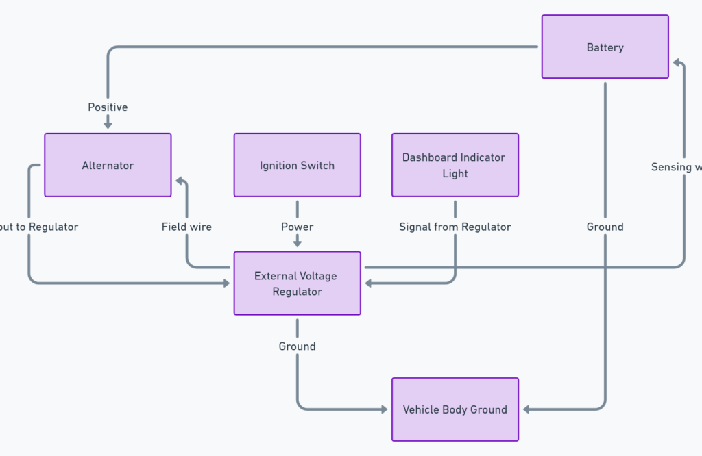
The main power sources will be the ALT and BAT wires:
- ALT – Connects to the output terminal of the alternator. Provides alternating voltage from the charging system.
- BAT – Connects to the positive terminal of the battery. Provides 12 volt DC power for the regulator operation.
2. Voltage Sensing
Two sense wires provide voltage feedback to the regulator:
- S – Sense wire attached to the battery positive terminal senses voltage directly at battery.
- F – Field wire connects to the field terminal on alternator which indirectly senses charging voltage.
3. Voltage Adjustment
The regulator has a voltage adjustment screw or potentiometer that sets the target charging voltage setpoint. This is usually around 13.5 to 14.5 volts.
4. Alternator Excitation
An exciter wire provides current to energize the alternator’s rotor field windings which enables it to generate power. This wire may be labeled “4”, “R”, or “I” on regulator pinouts.
5. Other Wires
- Indicator light wires connect to warning lights on the dash.
- Resistors may be wired in to drop/limit current to lights or other components.
Now that we understand the main components, let’s look at a wiring example.
Example Dodge External Regulator Diagram
Below shows an example early-80’s Dodge external voltage regulator wiring schematic:
Key Points:
- The main power feeds are BAT (battery) and ALT (alternator).
- Sense wires F (field) and S (sensing) provide voltage feedback.
- The exciter wire energizes the alternator to start generating power.
- Warning lights are wired from regulator posts to the dash light circuit.
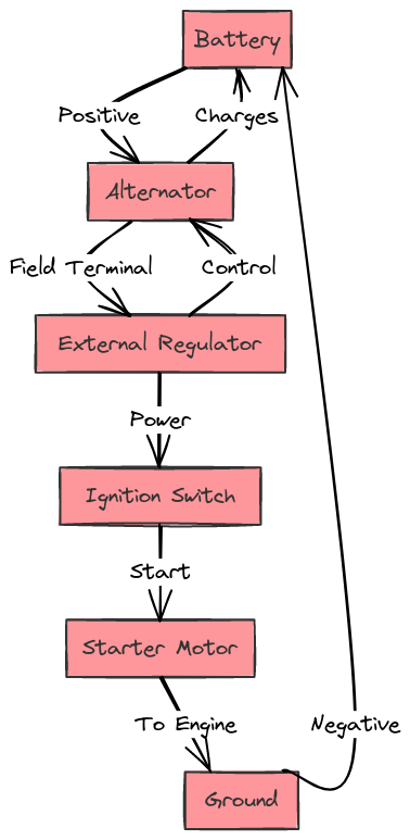
So in summary, this diagram shows the necessary wired connections to install an external Dodge regulator.
Tips for Diagnosing from External Regulator Diagrams
The diagrams provide valuable information for diagnosing charging issues. Here are quick tips for diagnosis:
1. Check sense wire connections – If there’s no charge voltage, disconnect sense wires and check for continuity. Replace wires if damaged.
2. Verify exciter circuit operation – No excitation means no alternator output. Test exciter wire for power during charging operation.
3. Check voltage setpoint adjustment – Over or undercharging could mean the regulator voltage adjustment needs alignment to specification.
4. Inspect warning light circuit – Non-functioning warning lights could indicate issues like a bad bulb/socket, resistor failure, or fried regulator.
Using the wiring diagram while systematically testing circuits can help identify faulty components. Most charging issues can be fixed with some diligent troubleshooting.
Conclusion
That covers the key points for reading and understanding external voltage regulator wiring diagrams on Dodge vehicles. To recap:
- The diagram shows power wiring, voltage sensing, regulator adjustment, alternator excitation and indicator lights.
- Following the wiring allows systematic diagnosis of charging circuit issues.
- Most problems can be discovered by methodically checking each circuit section.
Being able to accurately read and leverage the regulator diagram is critical for troubleshooting Dodge charging system problems. Hopefully this guide provides a good reference for becoming more familiar with these important wiring schematics.
Let me know if you have any other questions!
