Electrical Wiring Diagram
Electrical wiring diagrams are essential tools for understanding the intricate network of circuits and components that power our homes, buildings, and electronic devices. These visual representations provide a detailed roadmap of how electricity flows through a system, allowing electricians, engineers, and DIY enthusiasts to troubleshoot, maintain, and install electrical systems efficiently.
What’s Included in an Electrical Wiring Diagram?
An electrical wiring diagram typically includes the following components:
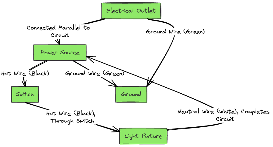
- Power source: This is the main input, such as a circuit breaker, fuse box, or outlet, that supplies electricity to the system.
- Wiring: The cables and conductors that carry the electrical current to various parts of the system.
- Switches, outlets, and fixtures: These are the points where electricity is distributed and used, such as light switches, power outlets, and light fixtures.
- Electrical devices: Any components that consume or control the flow of electricity, such as motors, appliances, and control panels.
- Grounding and bonding: The connections that ensure the safe and proper grounding of the electrical system.
How to Read an Electrical Wiring Diagram
Reading an electrical wiring diagram can seem daunting at first, but with a bit of practice, it becomes a valuable skill. Here’s a step-by-step guide:
- Identify the power source: Locate the main power input, such as a circuit breaker or fuse box, to understand where the electricity is coming from.
- Follow the wiring: Trace the wires and cables to see how they connect the various components in the system.
- Understand the symbols: Electrical diagrams use standardized symbols to represent different components, such as switches, outlets, and devices. Familiarize yourself with these symbols to interpret the diagram.
- Determine the purpose: Identify the specific function or purpose of the electrical system, whether it’s lighting, power distribution, or a specialized application.
- Identify potential issues: Examine the diagram for any potential problems, such as overloaded circuits, improper grounding, or outdated components.
Electrical Wiring Diagrams
Diagram 1:

Diagram 2:

Diagram 3:

Diagram 4:

Common Types of Electrical Wiring Diagrams
Electrical wiring diagrams come in various forms, each designed to serve a specific purpose:
- Schematic diagrams: These diagrams focus on the logical connections between components, rather than their physical layout.
- Pictorial diagrams: These diagrams use images and drawings to represent the actual physical placement and appearance of the components.
- Single-line diagrams: These simplified diagrams use a single line to represent a circuit, making them useful for quickly understanding the overall system.
- Wiring diagrams: These detailed diagrams show the precise physical layout and connections of the electrical components and wiring.
Interpreting Electrical Wiring Diagrams for Troubleshooting and Installation
Electrical wiring diagrams are essential for troubleshooting and installing electrical systems. By understanding the diagram, you can:
- Identify the cause of electrical issues: Use the diagram to trace the wiring and locate the source of any problems, such as a malfunctioning switch or a short circuit.
- Ensure proper installation: Follow the diagram to correctly install new electrical components, ensuring they are connected to the right power sources and integrated into the overall system.
- Upgrade or modify the system: Use the diagram to plan and execute any changes or upgrades to the electrical system, such as adding new outlets or replacing outdated components.
Conclusion
Electrical wiring diagrams are powerful tools that help us understand and manage the complex networks of electricity that power our modern world. By learning how to read and interpret these diagrams, you can become a more informed and confident electrician, homeowner, or DIY enthusiast, able to tackle a wide range of electrical projects with ease.


