Fuel Injector Wiring Diagram
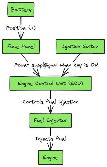
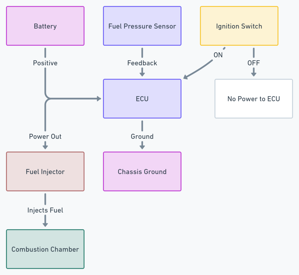
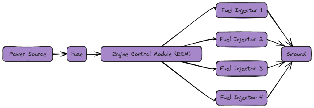
A fuel injector wiring diagram is a essential tool for understanding the inner workings of your car’s fuel system. This diagram provides a detailed visual representation of how the fuel injectors, sensors, and other components are connected, allowing you to troubleshoot issues, perform maintenance, or even upgrade your vehicle’s fuel system. By understanding the fuel injector wiring diagram, you can gain a deeper appreciation for the complex engineering that goes into modern automotive design.
Components of a Fuel Injector Wiring Diagram
A fuel injector wiring diagram typically includes the following key components:
- Fuel Injectors: These are the crucial components that spray the precise amount of fuel into the engine’s cylinders, ensuring efficient combustion.
- Fuel Pump: The fuel pump is responsible for delivering fuel from the tank to the fuel injectors under high pressure.
- Fuel Pressure Regulator: This component maintains the correct fuel pressure to the fuel injectors, ensuring optimal engine performance.
- Engine Control Unit (ECU): The ECU is the “brain” of the vehicle, responsible for controlling and monitoring the fuel system, as well as other critical systems.
- Sensors: Various sensors, such as the oxygen sensors and the manifold absolute pressure (MAP) sensor, provide the ECU with real-time data about the engine’s operating conditions.
Fuel Injector Wiring Diagrams
Diagram 1:

Diagram 2:

Diagram 3:

Diagram 4:

How to Read a Fuel Injector Wiring Diagram
Reading a fuel injector wiring diagram can seem daunting at first, but with a little practice, it becomes a valuable skill. Here’s a step-by-step guide:
- Identify the components: Familiarize yourself with the different components of the fuel system, such as the fuel injectors, fuel pump, and sensors.
- Follow the wiring: Trace the wires from each component to understand how they are connected to the ECU and the power source.
- Understand the color coding: Wiring diagrams often use color-coding to differentiate between different circuits and signals.
- Identify the ground points: Look for the grounding points, where the wires are connected to the vehicle’s body or chassis.
- Analyze the signal flow: Understand how the signals from the sensors and the ECU control the operation of the fuel injectors and other components.
Troubleshooting with a Fuel Injector Wiring Diagram
A fuel injector wiring diagram can be an invaluable tool when it comes to troubleshooting issues with your car’s fuel system. By using the diagram, you can:
- Identify wiring issues: If a fuel injector is not functioning correctly, the wiring diagram can help you locate the problem, whether it’s a loose connection, a short circuit, or a broken wire.
- Diagnose sensor problems: If a sensor is not providing accurate readings to the ECU, the wiring diagram can help you trace the signal path and identify the issue.
- Verify component operation: By following the wiring diagram, you can test the individual components, such as the fuel pump or the fuel pressure regulator, to ensure they are working correctly.
Upgrading Your Fuel System
In addition to troubleshooting, a fuel injector wiring diagram can also be helpful when upgrading your car’s fuel system. Whether you’re installing larger fuel injectors, a high-performance fuel pump, or a more advanced ECU, the wiring diagram can guide you through the process, ensuring that all the components are properly connected and integrated.
Conclusion
A fuel injector wiring diagram is a essential tool for anyone who wants to understand, maintain, or upgrade their car’s fuel system. By familiarizing yourself with the components and the wiring, you can gain a deeper appreciation for the engineering that goes into modern automotive design, and you’ll be better equipped to tackle any issues that may arise. Whether you’re a DIY enthusiast or a professional mechanic, a fuel injector wiring diagram is a valuable resource that can help you keep your vehicle running at its best.
