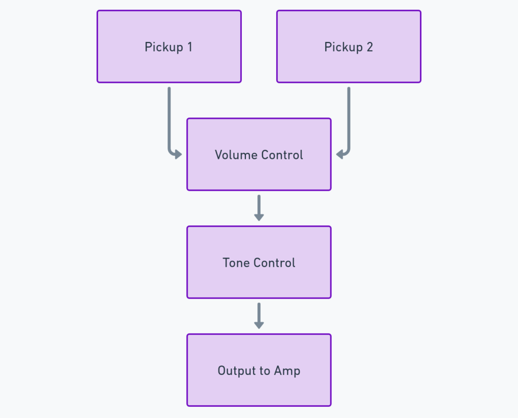
Guitar Wiring Diagrams 2 Pickups 1 Volume 1 Tone
The electronics in an electric guitar convert the vibrations of the strings into an electrical signal that can then be amplified. Here are the main components:
Pickups – Electromagnetic devices under the strings that produce a signal when metal guitar strings vibrate within their magnetic field. Common types are single-coil and humbucker.
Volume and Tone Controls – Allow you to control the output level and frequency response.
Switch – Selects between pickups. Often a 3-way toggle switch.
Output Jack – Where you plug in the guitar cable to connect to an amp.
Understanding how these components connect is key to wiring your guitar properly. This is where wiring diagrams come in handy.
Guitar Wiring Diagrams 2 Pickups 1 Volume 1 Tone
Diagram 1:

Diagram 2:

Diagram 3:

Diagram 4:

Diagram 5:

How to Read a Guitar Wiring Diagram?
At first glance, a wiring diagram can look confusing, with lots of pickup connections, grounds, capacitors and switches. But they can actually be simple to understand if you go through them methodically.
Here are some tips:
- Follow the Lines – Trace the path of each wire connector to see its endpoints and components along the way.
- Use Color Coding – Many diagrams color code the wire connections to make tracing easier. Often copper wires are orange and ground wires are green.
- Label All Parts – Good diagrams will clearly label pickups, controls and switches. Identify these and orient yourself.
- Find the Signal Path – Trace the path of an electrical signal from the pickups through the controls to see how it can be modified along the way.
Breaking Down the Key Components
Looking at this diagram component by component makes deciphering it a step-by-step process. Here are the key features:
Two Single Coil Pickups
We have two separate pickups labeled “STRAT SINGLE COIL PICKUP” with + and – terminals. Each one produces a signal that can be sent to the output independently.
1 Volume Control
A single 250k potentiometer labeled “VOLUME” acts as the volume control to set the output level. The pickups connect to the outer terminals with signal wires. The signal can be tapped from the center lug to send to output.
1 Tone Control
Similarly, a single 250k potentiometer labeled “TONE” serves as the tone control, allowing high frequencies to be rolled off to ground in the center lug. The pickups wire to the outer lugs to send signal through the tone circuit.
3-Way Toggle Switch
A switch labeled “TOGGLE SWITCH” has 6 lugs, allowing it to connect all three pickup combinations – Neck, Bridge, and Both. The switch routes signals from the pickups to the controls.
Output Wires
Finally, the volume circuit center lug connects the signal through shielded wires to the output jack, labeled “OUTPUT JACK”. The ground wire completes the circuit.
Final Thoughts
Walking through each component, input and output demonstrates how a guitar wiring diagram uses visual language to map the electronic connections and signal flow that brings your guitar to life.
While reading diagrams takes practice, a methodical approach can help decode even complex schemes. Understanding your existing wiring or diagram found online is crucial to successfully modifying or troubleshooting your guitar.
So don’t be intimidated by the mess of wires next time your stratocaster is cracked open. Follow the lines and use the tips covered here to leverage wiring diagrams to master your guitar’s electronics.
