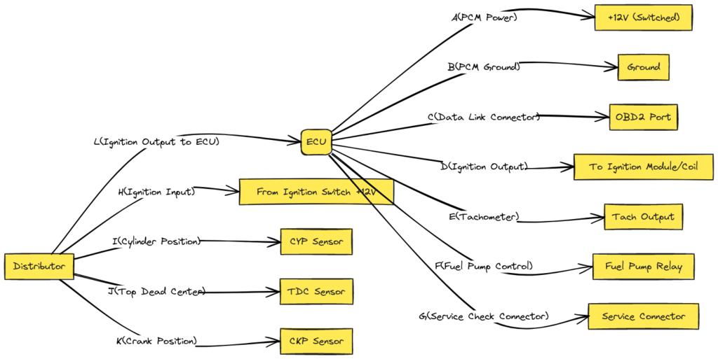
Honda OBD2 Distributor Wiring Diagram
The distributor is a crucial engine component that routes thousands of volts of electricity from the ignition coils to the spark plugs in a specific firing order. It has a rotor and cap to distribute the spark to cylinders.
Honda vehicles have used a variety of distributor-based and distributorless ignition systems over the years. Most 1996+ models utilize a distributor with an onboard computer controlled ignition system, known as OBD2. This stands for On-Board Diagnostics version 2, referring to the computer’s self-diagnostic capability.
The OBD2 distributor wiring connects the electronic brain of the vehicle to the mechanical timing function of the distributor. Understanding the diagram is key to pinpointing ignition problems.
Honda OBD2 Distributor Wiring Diagrams
Diagram 1:

Diagram 2:

Diagram 3:

Diagram 4:

Diagram 5:

Main Components of Honda’s OBD2 Distributor System
The two main components are:
1. ECU Computer
This is the engine control unit or electronic control unit (ECU). It is the central computer controlling ignition timing, fuel delivery, emissions controls, and more.
It receives sensor data and activates relays, solenoids, and actuators while diagnosing problems.
2. Ignition Control Module
This module is the intermediary between the ECU and the mechanical distribution of spark. It converts signals from the computer into powerful charges sent to the coils and spark plugs.
On 90’s Honda’s, this module is integrated on the distributor housing itself in most models. The wiring connects it to sensors and the PCM.
Honda OBD2 Distributor Wiring Diagram Overview
Now that we understand the key components involved, let’s breakdown the different electrical circuits in a simplified OBD2 Honda wiring diagram:
- Power Source Circuit – Provides 12V power from battery to system components
- Crankshaft Sensor Circuit – Sends crank position and engine speed data to ECU
- Camshaft Sensor Circuit – Reports cam position to assist with timing
- Vehicle Speed Sensor – Allows tuning timing for acceleration/deceleration
- Coolant Sensor – Monitors engine temperature
- Oxygen Sensor – Provides air/fuel ratio feedback to the PCM
- Ignition Control Module – Routes ECU signals to trigger coil primary/secondary current
- Ignition Coil Circuits – Steps up voltage for spark plugs from 12V battery to 25,000+ volts
As you can see, there are inputs telling the ECU what is happening mechanically, and outputs actuating the proper sparking events.
How to Read the Honda OBD2 Distributor Pinout Diagram
Now we’ll break down the wiring pinout diagram color codes and connections step-by-step:
- Thick Red Wire – This lead goes to the positive 12 volt terminal on the battery. This source power is distributed to various system components.
- Thick Black Wire – Routes to the negative ground terminal on battery, completing the power circuits.
- Red/Black Wire – Goes to the ignition coil which steps up the voltage for the spark plugs.
- Green Connector – This mates with the 4-pin camshaft position sensor. It reports back to the ECU the correlation between cam angle and crank position.
- Blue Connector – Attaches to the crankshaft sensor which reads position/RPM of crank pulley. This gives primary engine speed input.
- Black/Yellow Connector – Plugs into vehicle speed sensor. Allows ignition timing to be tuned for acceleration/deceleration.
- 2-Wire Brown Connector – Runs to coolant temperature sensor for cold start fuel enrichment modifications.
- Black Round Wire – Grounds different components and shielding.
And that sums up the basics of understanding this wiring system! Of course every make/model has variations, but this covers the major circuits.
Final Thoughts
Learning to navigate the Honda OBD2 distributor wiring diagram might seem intimidating initially. However, by understanding the main components involved and functions of each wire, you can diagnose and fix basic ignition issues. This saves time and money compared to blindly replacing parts during troubleshooting.
Refer to authorized service manuals for specifics on your vehicle’s pinout and connectors. And don’t hesitate to consult a professional technician for complex repairs. But for general knowledge or simple DIY repairs, hopefully this overview gets you comfortable working with this integral system.
