Honda Ruckus Wiring Diagram
The Honda Ruckus is a popular scooter known for its rugged durability and customization options. Like any vehicle, properly understanding and maintaining its electrical system is key to keeping a Ruckus running its best. That’s where the Ruckus wiring diagram comes into play.
Honda Ruckus Wiring Diagrams
Diagram 1:

Diagram 2:

Diagram 3:

Diagram 4:

Diagram 5:

What’s Included in the Ruckus Wiring Diagram
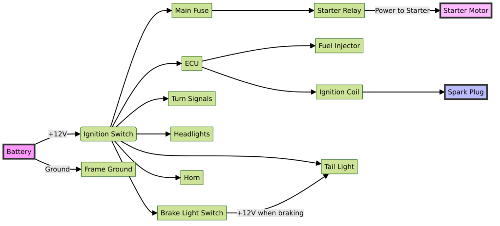
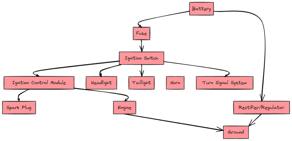
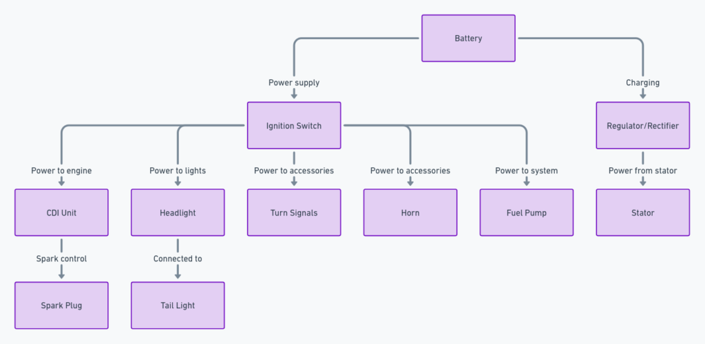
The Ruckus wiring diagram is a schematic that outlines the various electrical circuits and components of the scooter. Here’s an overview of what’s included:
- Main wire harnesses – Shows the bundles of wires connecting major components
- Fuse box – Identifies the key fuses protecting electrical systems
- Switches – Illustrates switches for lighting, signals, ignition, etc.
- Lights – Maps out wiring for headlight, brake light, turn signals, etc.
- Battery – Traces the positive and negative battery cables
- Relays – Highlights power relays for starter, fan, and other components
- Sensors – Identifies sensors providing key input signals to the ECU
- ECU – Maps input and output pins on the Engine Control Unit
- Other components – Includes various sensors, solenoids, rectifier, CDI unit, and more
Overall, the diagram provides a central reference for tracing electrical power and signal flows across the entire scooter.
How to Read the Honda Ruckus Wiring Schematic
Here are some key tips for navigating a Ruckus wiring diagram:
- Follow the colors – Literally. The diagram color-codes wires and components to help track individual circuits.
- Identify splices – When a solid line splits into multiple paths, this indicates a splice or connection point.
- Inspect symbols – The diagram uses standard symbols to denote components instead of pictorial representations. Learn these symbols.
- Note wire paths – Pay attention to what sections, components, and devices certain wires are connecting.
- Reference numbers – Components and connectors often include numbered labels, which correspond to identifiers in service manuals.
- Learn harness routes – Study how major wire bundles connect to different sections of the vehicle.
- Trace troubles – Methodically follow circuits to isolate faults during troubleshooting and repairs.
With some study of the schematic symbols and colors, you can navigate the web of wires more easily to understand the Ruckus electrical systems.
Final Thoughts on the Ruckus Wiring Setup
The Ruckus utilizes an advanced wiring schematic to connect and command its various electrical components. While complex at first glance, methodically tracing and learning this diagram is crucial for monitoring, maintaining, and customizing your Ruckus scooter. The colors, symbols, wire routes, and labels provide a map for diagnosing issues or even upgrading parts.
Whether optimizing performance or repairing key electrics, the Ruckus wiring diagram should be the go-to guide every Ruckus owner has on hand. With some dedicated study, you can better grasp this roadmap to your scooter’s nervous system. Then you can keep those critical electrons flowing for many more miles of Ruckus riding fun.
