Intellitec Electronic Climate Control Wiring Diagram
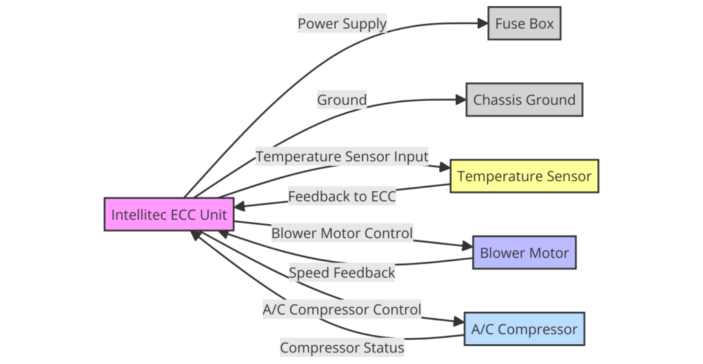
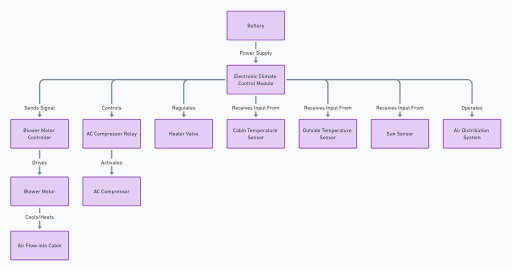
The Intellitec electronic climate control wiring diagram is a vital resource for anyone working with heating, ventilation, and air conditioning (HVAC) systems in recreational vehicles (RVs) or related applications. This detailed schematic provides a visual representation of the electrical connections and components involved in the climate control system, facilitating troubleshooting, installation, and maintenance tasks.
What’s Included in the Diagram?
The Intellitec electronic climate control wiring diagram typically encompasses the following key elements:
- Control Board: This is the brain of the system, responsible for processing input signals and sending commands to various components.
- Thermostat: The thermostat acts as the user interface, allowing you to set the desired temperature and adjust other settings.
- Air Conditioner: The diagram illustrates the wiring connections for the air conditioning unit, including the compressor, fan motor, and other related components.
- Furnace: The furnace wiring is depicted, showcasing the connections for the ignition system, blower motor, and safety devices.
- Power Supply: The diagram highlights the power supply connections, including battery or shore power sources, and any necessary voltage regulators or converters.
- Sensors: Temperature sensors, humidity sensors, and other input devices are represented, indicating their wiring connections to the control board.
- Relays and Switches: Various relays, switches, and other control components are shown, enabling the system to activate or deactivate specific functions based on user input or environmental conditions.
Intellitec Electronic Climate Control Wiring Diagrams
Diagram 1:

Diagram 2:

Diagram 3:

How to Read the Wiring Diagram
Reading an Intellitec electronic climate control wiring diagram may seem daunting at first, but with a little guidance, it becomes relatively straightforward. Here are some tips to help you navigate the schematic:
1. Understand the Symbols and Conventions
Wiring diagrams use standardized symbols to represent different components and connections. Familiarize yourself with the legend or key provided, which explains the meaning of each symbol used in the diagram.
2. Trace the Connections
Follow the wiring lines and connections between components, paying close attention to the color codes or labels used. This will help you understand how the various elements are interconnected and how signals flow through the system.
3. Identify Power Sources and Ground Connections
Locate the power sources (battery, shore power, etc.) and ground connections on the diagram. These are crucial for ensuring proper operation and preventing potential electrical issues.
4. Note Component Specifications
Some diagrams may include additional information, such as component ratings, part numbers, or voltage/amperage requirements. This information can be valuable when troubleshooting or replacing components.
Troubleshooting and Maintenance
One of the primary uses of the Intellitec electronic climate control wiring diagram is for troubleshooting and maintenance purposes. By following the diagram, you can:
- Identify Faulty Components: If a specific component is not functioning correctly, the diagram can help you trace the wiring connections and isolate the potential issue.
- Check Electrical Continuity: Use a multimeter to verify electrical continuity along the wiring paths depicted in the diagram, ensuring proper connectivity.
- Verify Correct Wiring: When installing or replacing components, the diagram serves as a reference to ensure proper wiring connections are made.
- Understand System Operation: By studying the diagram, you can gain a better understanding of how the various components interact and operate within the climate control system.
Safety Considerations
Working with electrical systems always carries inherent risks. When using the Intellitec electronic climate control wiring diagram, it’s essential to follow proper safety precautions:
- Disconnect Power Sources: Before performing any work on the system, ensure that all power sources (battery, shore power, etc.) are disconnected to prevent electrical shocks or shorts.
- Use Proper Tools: Employ insulated tools and follow recommended safety practices when working with electrical components.
- Consult Professionals: If you’re unsure about any aspect of the wiring or system operation, it’s advisable to consult with a qualified professional or seek assistance from Intellitec support.
Conclusion
The Intellitec electronic climate control wiring diagram is an indispensable resource for anyone dealing with RV HVAC systems. By understanding the components, connections, and overall system operation depicted in the diagram, you can effectively troubleshoot issues, perform maintenance tasks, and ensure the proper functioning of your climate control system. Remember to follow safety guidelines and seek professional assistance when necessary to ensure a successful and safe experience.
