Jeep CJ5 Wiring Diagram
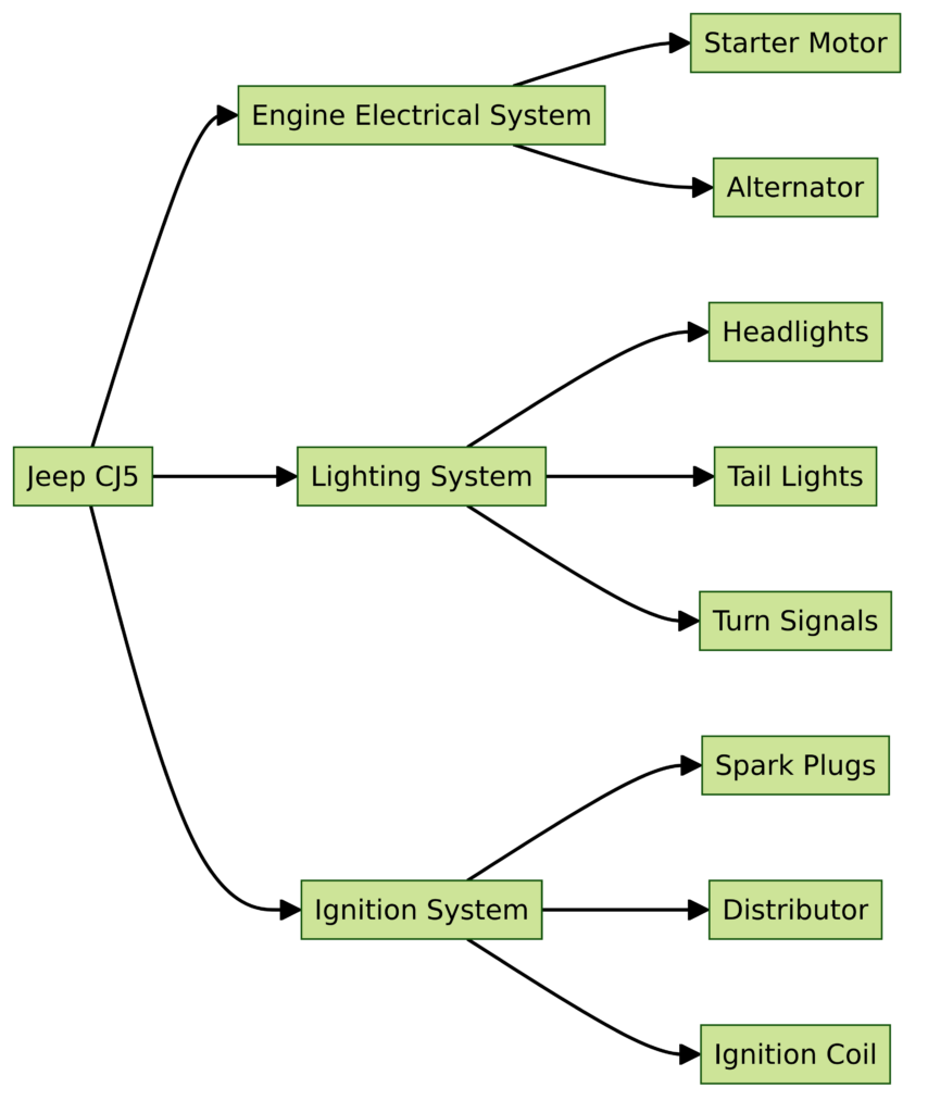
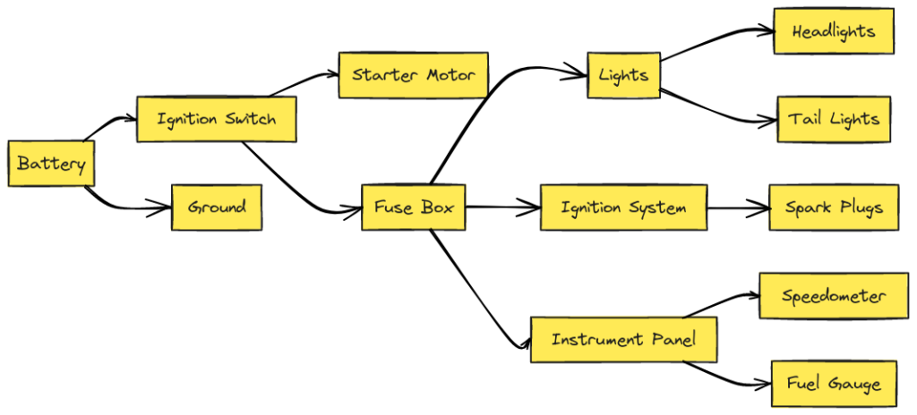
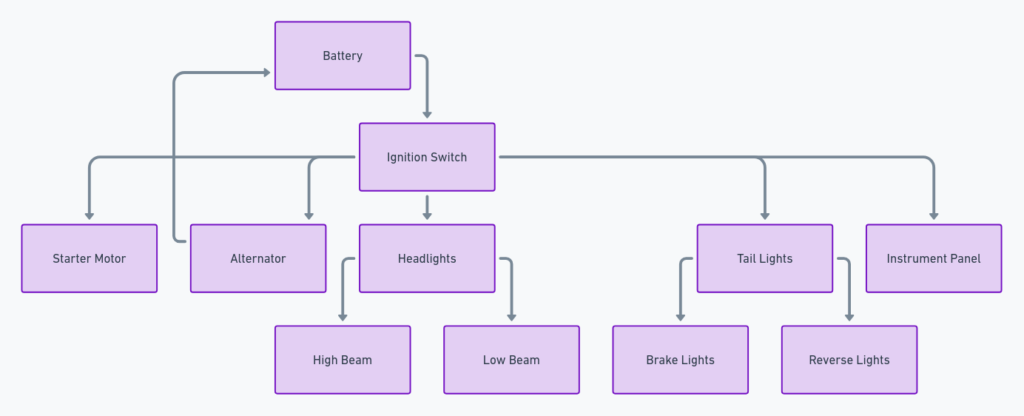
The Jeep CJ5 wiring diagram is a visual representation of the vehicle’s entire electrical system. It illustrates the various components, such as the battery, alternator, fuse box, lights, gauges, and switches, along with their interconnections via color-coded wires. This invaluable resource provides a roadmap for tracing electrical circuits, identifying potential issues, and ensuring proper functionality.
Here’s a breakdown of what you can expect to find in the Jeep CJ5 wiring diagram:
- Battery and Charging System: This section outlines the connections between the battery, alternator, and voltage regulator, ensuring a reliable power supply for your Jeep.
- Fuse Box and Relay Panel: The diagram details the layout of the fuse box and relay panel, allowing you to pinpoint the location of specific fuses and relays for troubleshooting purposes.
- Lighting System: From headlights to taillights and interior illumination, this section covers the wiring for all lighting components, ensuring you can navigate safely in any condition.
- Gauges and Instruments: The wiring for the speedometer, tachometer, fuel gauge, and other instrument cluster components is depicted, aiding in accurate readings and diagnostics.
- Switches and Controls: This part of the diagram illustrates the wiring for various switches and controls, such as turn signals, wipers, and heating/cooling systems, enabling you to identify and resolve any issues with ease.
- Accessories and Additional Circuits: If you’ve added aftermarket accessories or modified your Jeep CJ5, this section can help you integrate them seamlessly into the existing wiring system.
Jeep CJ5 Wiring Diagrams
Diagram 1:

Diagram 2:

Diagram 3:

Diagram 4:

Diagram 5:

How to Read the Jeep CJ5 Wiring Diagram
Reading a wiring diagram might seem daunting at first, but with a few simple tips, you’ll be navigating it like a pro in no time:
- Familiarize Yourself with the Symbols: The diagram uses standardized symbols to represent various components, such as switches, relays, and ground connections. Take some time to understand the meaning of each symbol.
- Follow the Wire Colors and Paths: Each wire is color-coded, making it easier to trace its path from one component to another. Pay close attention to these colors and follow the wires carefully.
- Understand the Connectors: The diagram will show connectors, which are points where multiple wires come together. These connectors are labeled and can help you identify the specific location of a component or circuit.
- Cross-Reference with the Legend: Most wiring diagrams come with a legend that explains the abbreviations, symbols, and wire colors used. Refer to this legend whenever you’re unsure about a particular element.
- Start Simple and Work Your Way Up: If you’re new to wiring diagrams, begin with a straightforward circuit, such as the headlight or turn signal system, before tackling more complex ones.
