John Deere 318 Wiring Diagram
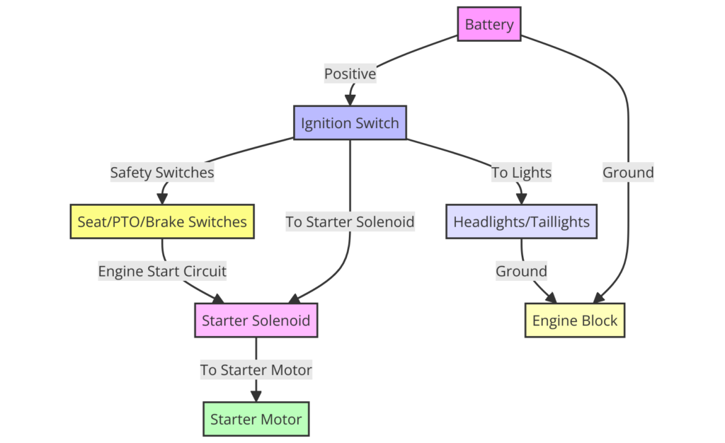
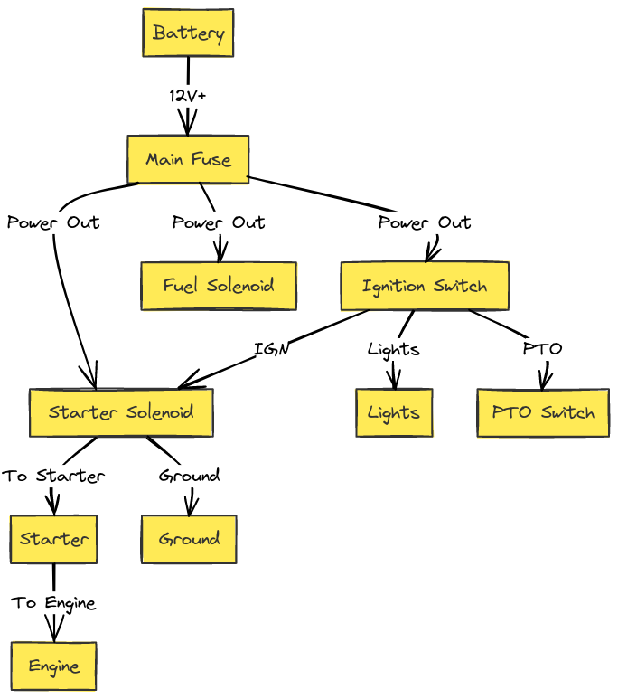
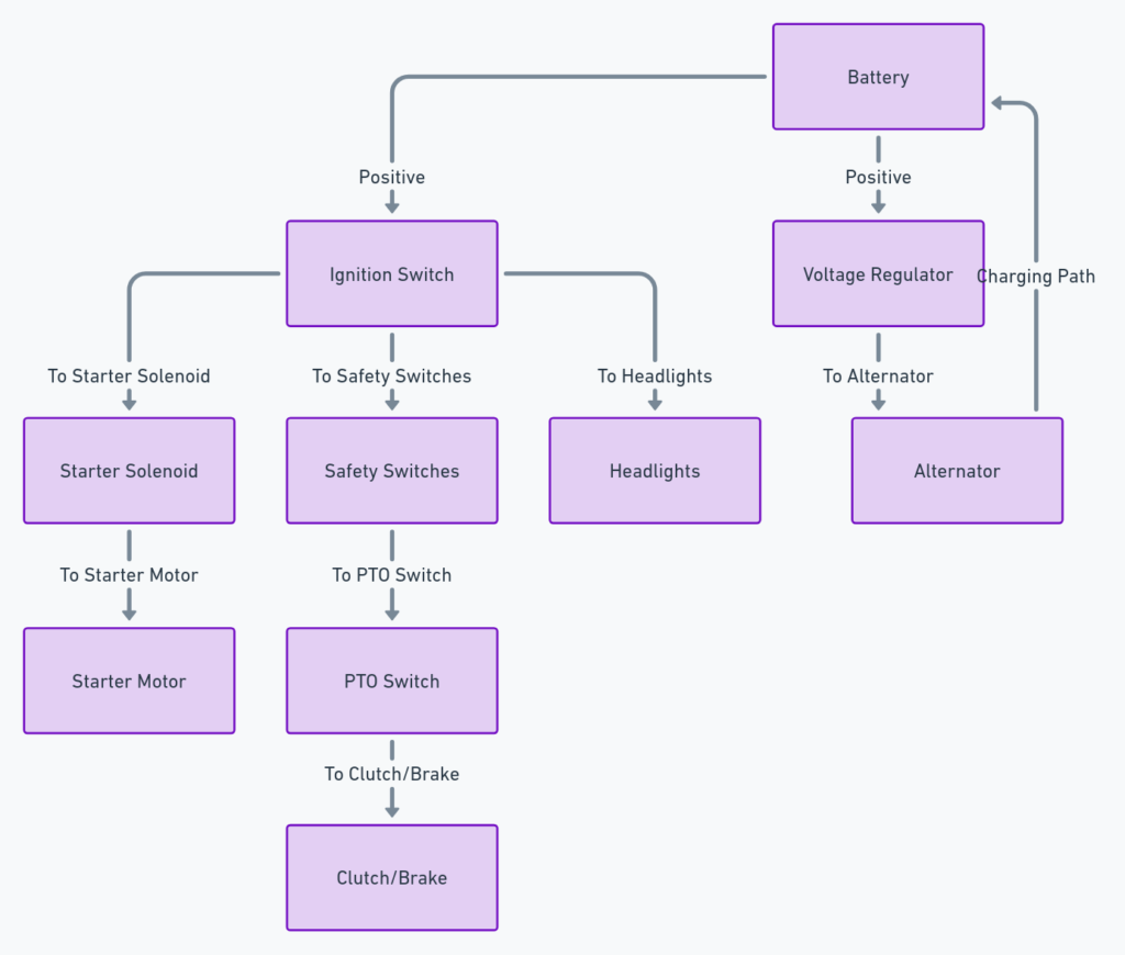
The wiring diagram for the John Deere 318 is a schematic that outlines the tractor’s electrical system. It shows how power flows from the battery to the various components and accessories.
The 318 wiring diagram includes:
- Fuse box connections
- Starter circuit
- Alternator charging circuit
- Wire harness routing
- Lighting circuits (headlights, warning lights, etc.)
- Accessory power outlets
- Solenoid and safety switch placements
- Instrument panel/gauge connections
Knowing how to decipher the diagram is crucial for properly troubleshooting electrical issues on your John Deere 318.
John Deere 318 Wiring Diagrams
Diagram 1:

Diagram 2:

Diagram 3:

Diagram 4:

Diagram 5:

How to Read the John Deere 318 Wiring Diagram?
When looking at the 318 wiring diagram, you’ll notice lots of lines and symbols. Here are some tips for understanding what everything represents:
- Lines indicate wires or wire harnesses. Different line styles (solid, dashed, thick, thin) denote different components.
- Symbols represent electrical components like fuses, grounds, switches, relays, lights, etc.
- Power distribution points are shown with larger dots.
- Labels identify circuits, wire gauges, connector pinouts, fuse amps, etc.
- Colored highlighting often indicates separate circuits or wire bundles.
- The diagram layout resembles the actual component layout on the tractor.
Follow lines from power sources to component symbols to understand current flow. Check labels to trace wires through connectors or find fuse/relay amp ratings. Understanding the meaning behind the diagram symbols is key.
Helpful Tips for Using the John Deere 318 Wiring Diagram
Here are some helpful recommendations when consulting the 318 wiring diagram for repairs or troubleshooting:
- Thoroughly inspect wiring harnesses for damage before replacing components. Frayed/pinched wires can mimic failed parts.
- Confirm battery voltage and ground connections are clean and secure first. Many issues stem from power supply.
- Verify wires at connectors match the wiring diagram pinouts.
- Check for continuity in sections of circuit suspected of faults. Isolate opens/shorts.
- Replace components one at a time to identify failed part. Confirm fix before moving to next suspect area.
- Carefully confirm wire routings if splicing in new wires or harnesses. Keep wiring tidy.
- Double check fuse locations/amperages if swaps don’t resolve blown fuses.
- Document corrections made to wiring with notes on the diagram for future reference.
Final Thoughts
Learning to read and apply the information on the John Deere 318 wiring diagram is an essential skill for DIY-ers carrying out repairs and modifications. The diagram connects the dots between electrical power supply and the components needing that power.
Tracing out circuits methodically, inspecting connections thoroughly, and testing systematically can solve most electrical gremlins. Pairing such troubleshooting techniques with the wiring diagram’s circuit layouts will get your John Deere 318 up and running again.
