John Deere 4020 12 Volt Wiring Diagram
The John Deere 4020 is one of the most popular tractors that Deere has ever produced. With over 200,000 units sold, it’s not hard to find one still going strong after decades of use. However, keeping these workhorse machines running requires an understanding of how they are wired, especially when it comes to the 12 volt electrical system.
John Deere 4020 12 Volt Wiring Diagrams
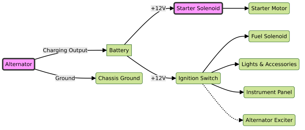
Diagram 1:

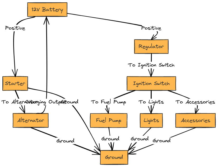
Diagram 2:

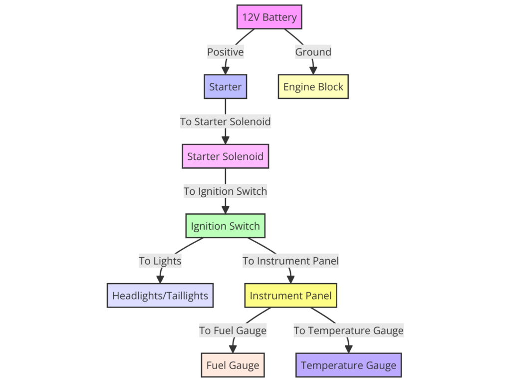
Diagram 3:

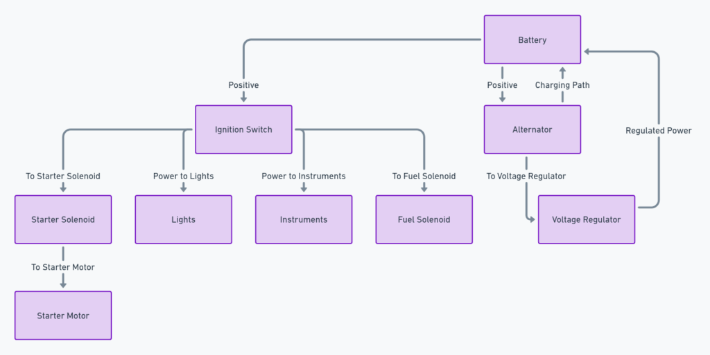
Diagram 4:

Diagram 5:

What’s Included in the John Deere 4020 12 Volt Wiring Diagram
The 4020 wiring diagram shows all parts of the 12 volt starting, charging, lighting and accessory systems in an easy to understand format. Here are some of the key components that the diagram outlines:
Battery and Cables
- The main tractor battery size and specifications
- Route of the positive and negative battery cables
- Connections to starter motor and alternator/voltage regulator
Solenoid and Starter
- Wiring route from battery to starter solenoid
- Connections from solenoid to starter motor
Alternator and Regulator
- Outlines alternator output to regulator
- Voltage regulator connections to battery, warning light and alt field
Lights and Accessories
- Headlight, tail light and gauge light circuits
- Wiring for accessories like PTO clutch, seat switch, etc.
Switches and Relays
- Key switch connections and functions
- Placement of safety switches and relays
How to Read the John Deere 4020 12 Volt Diagram
Reading wiring diagrams takes some practice but there are a few key things that make reading the 4020 12 volt diagram easy:
Use Colors and Symbols
- The diagram uses standard colors and symbols to represent different wire types
- For example, red wires indicate positive leads while blue is used for control wires
Follow the Route
- Arrows show the direction of current flow from source to component
- Dashed lines indicate the wiring connections between parts
Read Left to Right
- Generally the diagram flows from left to right
- The components on the left like the alternator and battery supply power to parts on the right
Labeling is Key
Clear labeling of parts and circuits makes understanding connections simple
By becoming familiar with these basic techniques, the 4020 12 volt diagram will transform into an easy-to-read roadmap for electrical troubleshooting and repair.
Final Thoughts on the John Deere 4020 12 Volt Diagram
The simple black and white wiring schematic contains a wealth of important information for keeping your vintage Deere tractor running. Taking the time to understand the diagram leads to faster diagnosis of electrical problems, proper testing procedures, and getting your 4020 back up running again quickly.
Deere engineers created a standardized wiring template across models which means once you learn to read one diagram, it gets easier to follow all of them. Mastery of diagram reading is an important skillset for any tractor owner or mechanic working to preserve these pieces of agricultural history.
So don’t let the diagram intimidate you. Spend some time identifying components and following the flow from beginning to end. It will be rewarding next time an electrical gremlin rears its head!
