John Deere Alternator Wiring Diagram
The alternator is a crucial component that charges the battery and powers electrical components while your John Deere engine is running. Once the engine starts, a belt-driven pulley rotates the alternator to generate power.
The key elements of John Deere alternator wiring include:
- Alternator
- Voltage regulator
- Battery
- Indicator light
- Associated wiring and connectors
Voltage is distributed from two terminals on the back of the alternator to components all over the equipment. An internal voltage regulator ensures voltage remains steady at 12-15 volts.
Without a properly working charging system, your John Deere machine will eventually lose power and shut off once the battery drains.
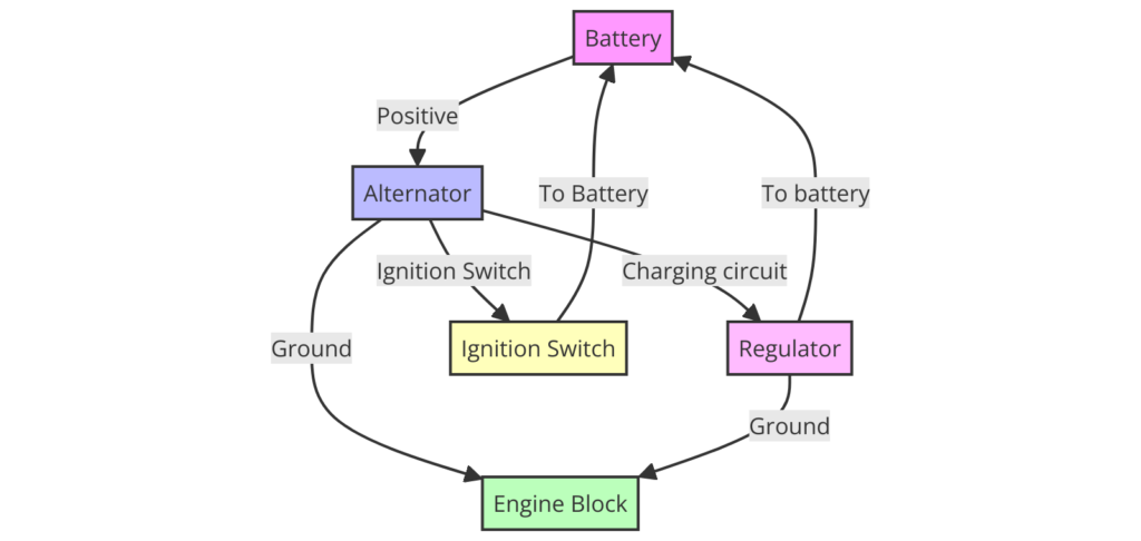
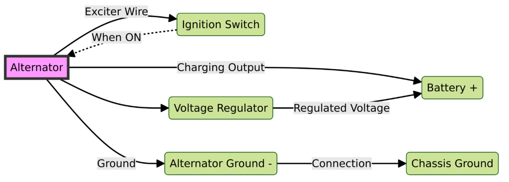
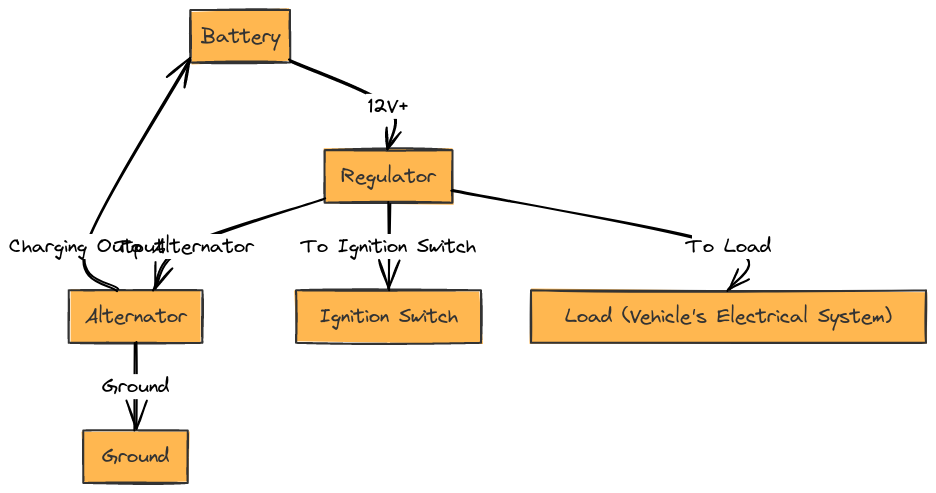
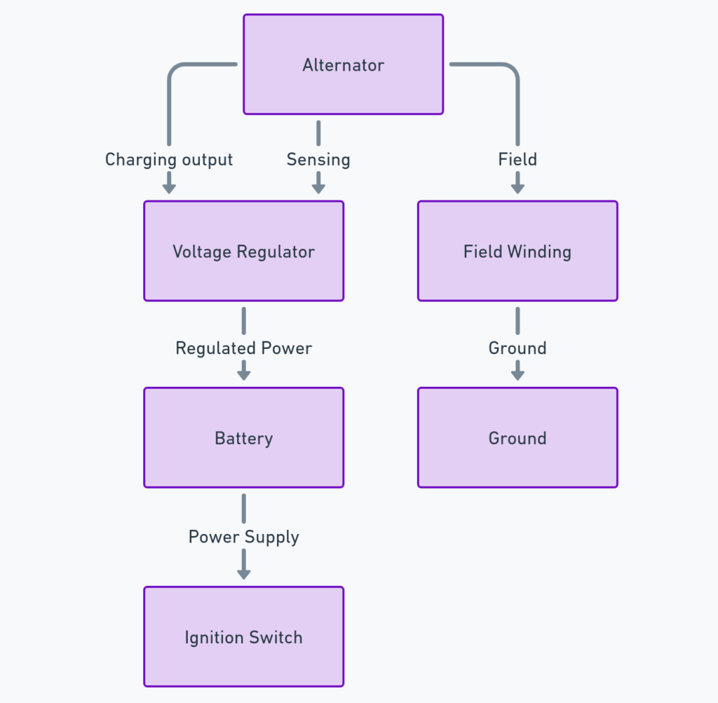
John Deere Alternator Wiring Diagrams
Diagram 1:

Diagram 2:

Diagram 3:

Diagram 4:

Diagram 5:

How to Read John Deere Wiring Diagrams
At first glance, an alternator wiring diagram can look complex and confusing with all the lines and symbols. However, there is a logic to it that becomes clear if you know what the basic symbols represent.
Here are some tips for reading John Deere alternator wiring diagrams:
- Multi-wire cables are depicted in one line rather than individual wires
- Different line styles indicate specific types of circuits
- Arrows show the direction of power flow
- Common symbols represent components like fuses, grounds, resistors
Additionally, diagrams are labeled with part codes you’ll find printed on the actual alternator and wiring connectors. Familiarizing yourself with the most common codes ahead of time saves time trying to interpret each diagram.
If available, referring to spec sheets from the John Deere parts catalog provides further information to properly identify wiring and connectors.
With some focused analysis, you’ll start to see orderly connections between essential components.
Key Components in John Deere Alternator Circuit
Though wiring varies across John Deere equipment, from older tractors to newer combines, the same basic components make up the alternator circuit.
Major components include:
Alternator
This belt-driven part powers all electrical systems while the engine runs. The internal voltage regulator ensures steady voltage to components.
Battery
Stores unused electricity from the alternator and provides initial power to start the engine.
Voltage Regulator
Regulates output from the alternator stator to maintain steady voltage of 12-15 volts. The regulator can be internal or external.
Indicator Light
Illuminates if the alternator circuit fails or battery isn’t charging properly. This alerts the operator.
Wiring & Connections
Cables and plugs connect components. Failure points that disable the system.
Understanding the function of each component helps troubleshoot issues.
How to Troubleshoot from John Deere Alternator Wiring Diagrams
If you believe your battery is not charging properly or indicator light suggests an issue, the alternator wiring diagram is the place to start troubleshooting.
Follow these systematic steps for diagnosing problems:
- Inspect Connections – Loose or dirty connections can interrupt power flow. Check condition of connectors and terminal ends.
- Check the Belt – Verify intact belt from engine to alternator pulley. Replace if worn or damaged.
- Test Voltage Output – Using a multimeter, verify battery voltage. If low, test voltage readings at alternator terminals.
- Swap Components – Substitute a known good voltage regulator or alternator to isolate the bad part.
- Focus on Sensor Circuits – Sensor or temperature switch circuits can mimic a bad alternator. Test continuity through sensors.
Methodically test sections of the system while referring to the wiring diagram to pinpoint the root cause. Whether it’s a faulty connection, bad bearing or malfunctioning regulator, the diagram guides logical troubleshooting.
Final Thoughts on John Deere Alternator Wiring Diagrams
Understanding John Deere alternator wiring diagrams does not need to be an intimidating or frustrating task. While they appear complex at first, once you grasp some key fundamentals around how to read them and the critical components involved, diagnosing charging system issues can be straightforward.
The wiring diagram serves as an invaluable reference for logically stepping through connectors, regulator problems or component faults that can drain batteries and disable equipment. Use the tips outlined here to properly leverage these diagrams while troubleshooting.
Now you have the knowledge to keep your John Deere battery charged and electrically-powered components operational when you need them most.
