John Deere Starter Solenoid Wiring Diagram
Do you need help decoding a John Deere starter solenoid wiring diagram? As useful as these diagrams are for tracing electrical connections, they can appear complicated to the untrained eye. This guide will provide a simple introduction to reading and interpreting John Deere starter solenoid diagrams to help you properly wire or troubleshoot your machine.
What is a Starter Solenoid?
The starter solenoid is a critical component that acts as a switch to supply power from the battery to the starter motor, thus allowing the engine to be cranked or turned over for starting. It contains a plunger that slides into an electromagnet to make the connection when the start switch is engaged. The solenoid essentially regulates high current at low voltage.
Inside the solenoid, you’ll find:
- Electromagnet coils – Created from current flow to generate a magnetic field to retract the plunger
- Plunger – Connects to the motor when retracted
- Pull-in contacts – Thin “switch” contacts to deliver initial power to the electromagnets
- Hold-in contacts – Thicker contacts that can handle high current for the motor
Understanding these core solenoid components will help when reading a John Deere starter wiring diagram.
John Deere Starter Solenoid Wiring Diagrams
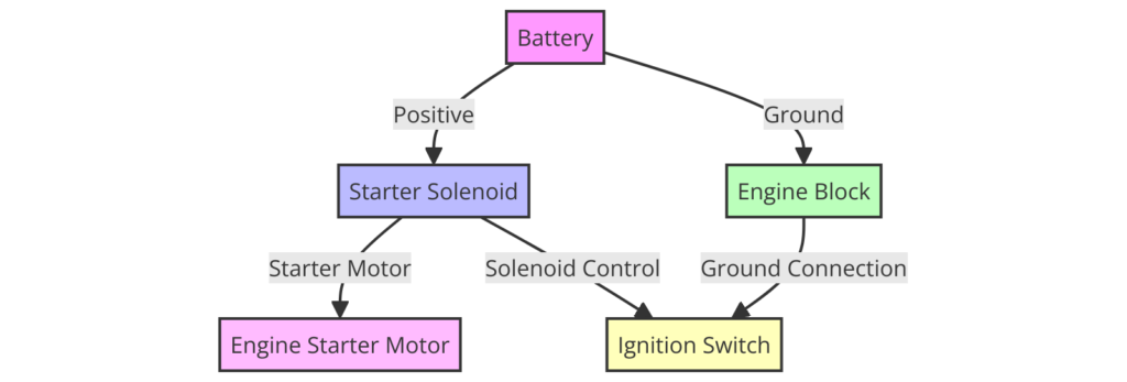
Diagram 1:

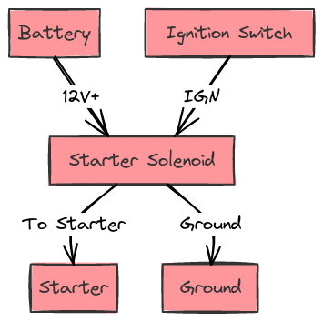
Diagram 2:

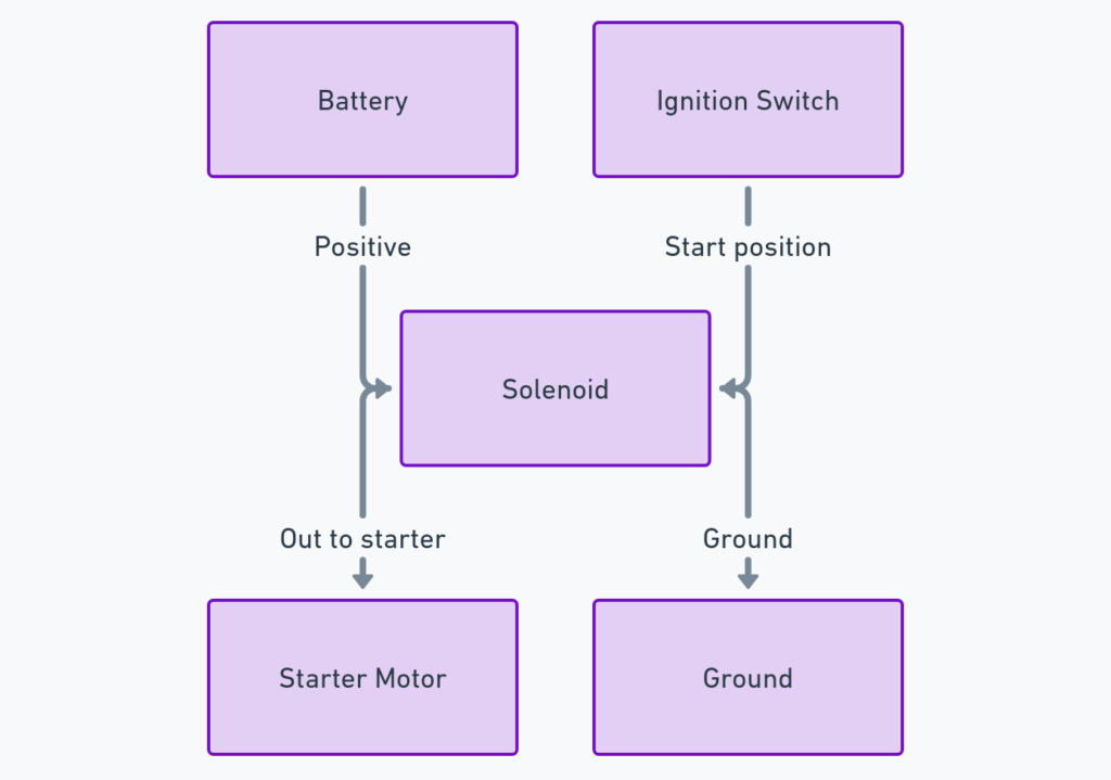
Diagram 3:

Diagram 4:

Diagram 5:

How to Read a John Deere Starter Solenoid Wiring Diagram
Here are some key tips for deciphering a John Deere starter solenoid wiring diagram:
1. Identify Wiring Connections
- Battery POS/NEG – Power source input to solenoid
- Starter Motor – Where power is sent to turn over the engine
- Pull Coil – Electromagnet that engages plunger when powered
- Hold Coil – Electromagnet that keeps plunger engaged
- START Switch – Dashboard switch that triggers solenoid
Tracing the flow from battery to starter motor is critical.
2. Understand Wire Gauge Differences
Note the diagram uses different line weights to denote wire gauges:
- Thick lines – High current wires for motor
- Thin lines – Lower current trigger wires
This helps trace circuit priority and flow.
3. Follow Dashed Line Flows
The dashed lines indicate the core internal connections inside the solenoid that you cannot physically see. This shows how current flows through the electromagnetic coils to the motor.
4. Check Contextual Info
Extra info like part numbers, specs, notes, ratings, etc can provide additional handy wiring details. Don’t ignore these!
With practice, you’ll begin to quickly interpret how the starter solenoid functions to start the motor.
Key Solenoid Terminology
Some other key terms you may encounter:
- Cranking – Turning over the engine via the starter motor
- Excitation – Applying current to create an electromagnetic field
- Plunger – Moved shaft to close high current contacts
- Pull-in coils – First coils to be excited to retract plunger
- Hold-in coils – Maintain plunger retraction during cranking
Familiarize yourself with these to talk the language!
Reading Complex John Deere Diagrams
More advanced John Deere starter wiring diagrams can appear intimidating at first glance. Here are some tips if encountering more complexity:
- Trace unconditionally – Follow every line one-by-one
- Note splits – Some wires may branch to other points
- Reference numbers – Cross-check versus other diagrams
- Leverage legends – Check diagrams keys to identify symbols
- Compare models – Note differences between machines
- Highlight flows – Use colors/pen to trace core paths
- Get specific help – Consult mechanics for complex jobs
While it takes practice, diligence pays off for correctly interpreting sophisticated John Deere solenoid wiring. Lean on diagrams for successful repairs or troubleshooting!
Conclusion
In summary, here are key points to remember:
- Starter solenoids engage the starter motor via a retractable electromagnet
- John Deere starter wiring diagrams use different line weights and flows
- You need to identify major wiring connections and components
- Note technical specs and terminology to understand contexts
- More complex diagrams just require more patience and tracing
I hope you now feel more empowered to take on that John Deere starter solenoid diagram. The key is to diligently follow the flows one step at a time. Please reach out with any other questions!
