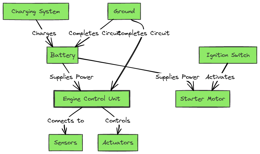
Kohler Command Kohler Engine Wiring Diagram
The Kohler Command engine is a popular choice for various outdoor power equipment, such as lawn mowers, generators, and pressure washers. Understanding the wiring diagram for your Kohler Command engine is crucial for troubleshooting, maintenance, and ensuring optimal performance. In this comprehensive guide, we’ll delve into the details of the Kohler Command engine wiring diagram, providing you with the knowledge to navigate and interpret this essential document.
What’s Included in the Kohler Command Wiring Diagram?
The Kohler Command engine wiring diagram typically includes the following components:
- Ignition System: This includes the spark plugs, ignition coils, and the engine’s ignition module or control unit.
- Fuel System: The wiring for the fuel pump, fuel solenoid, and fuel injection components (if applicable).
- Charging System: The alternator, voltage regulator, and any associated wiring.
- Safety Switches: Wiring for safety switches, such as the oil pressure switch and the engine kill switch.
- Sensors: Wiring for various sensors, including the temperature sensor, oil pressure sensor, and air-fuel ratio sensor.
- Electrical Accessories: Wiring for additional electrical components, like lights, gauges, and any aftermarket accessories.
Kohler Command Kohler Engine Wiring Diagrams
Diagram 1:

Diagram 2:

Diagram 3:

Diagram 4:

How to Read the Kohler Command Wiring Diagram
Reading the Kohler Command wiring diagram can seem intimidating at first, but with a bit of practice, it becomes a valuable tool for understanding your engine’s electrical system. Here are some tips to help you navigate the diagram:
- Identify Components: Familiarize yourself with the various components and their symbols in the diagram. This will help you easily locate and understand the connections between different parts of the engine.
- Follow the Wiring Paths: Trace the wires and connectors to understand how the different systems are linked together. This will help you identify any potential issues or areas that need attention.
- Understand Color Coding: Kohler often uses specific color-coding for their wiring, which can help you quickly identify different circuits and their functions.
- Refer to the Legend: Most wiring diagrams include a legend that explains the symbols and color-coding used. Refer to this legend to ensure you’re interpreting the diagram correctly.
Troubleshooting and Maintenance
The Kohler Command engine wiring diagram is an essential tool for troubleshooting and maintaining your engine. By understanding the diagram, you can:
- Identify Electrical Issues: If your engine is experiencing electrical problems, such as a malfunctioning ignition system or charging system, the wiring diagram can help you pinpoint the issue.
- Perform Maintenance: Regular maintenance, like replacing spark plugs or checking wiring connections, becomes easier with a clear understanding of the engine’s electrical system.
- Upgrade or Modify: If you’re planning to add new electrical components or accessories to your Kohler Command engine, the wiring diagram can guide you on how to properly integrate them.
Conclusion
The Kohler Command engine wiring diagram is a valuable resource for anyone who owns or works on these reliable engines. By understanding the components included in the diagram and how to interpret it, you can effectively troubleshoot, maintain, and even upgrade your Kohler Command engine. Whether you’re a DIY enthusiast or a professional technician, this guide will help you navigate the intricacies of the Kohler Command wiring diagram with confidence.
