Mobile Climate Control Wiring Diagram
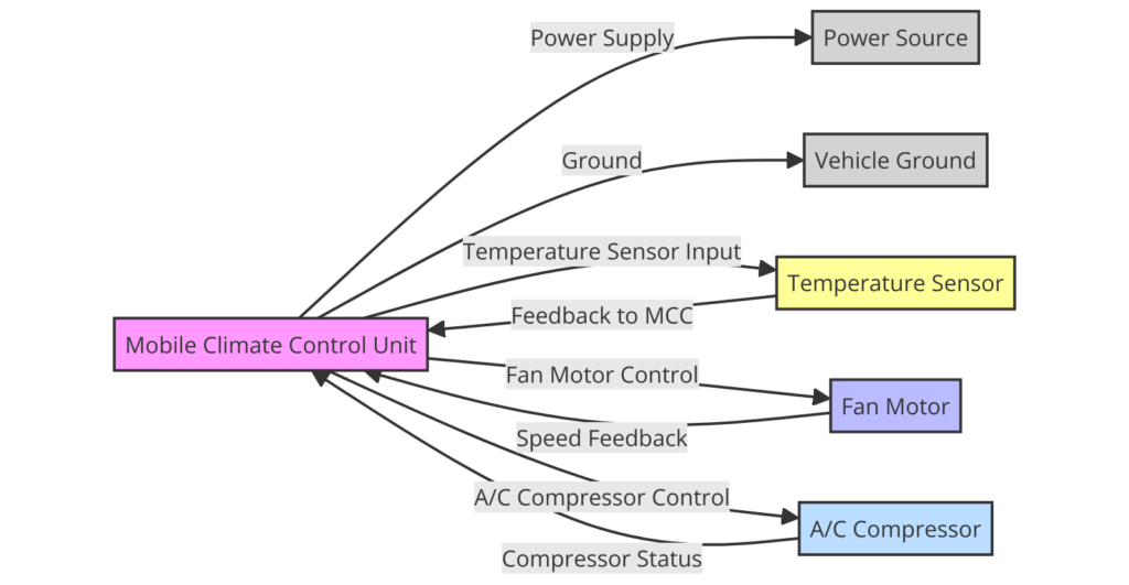
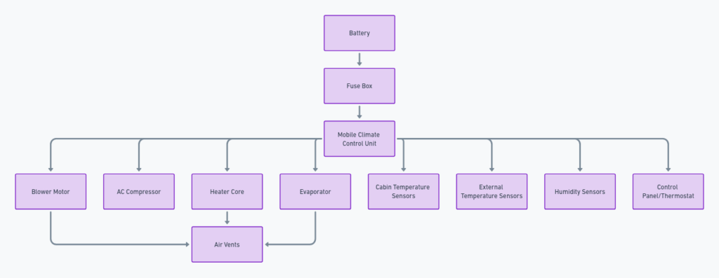
A mobile climate control wiring diagram is a visual representation of the electrical connections and components involved in the air conditioning and heating system of a vehicle. It serves as a roadmap for understanding how the various wires, sensors, and actuators work together to regulate the cabin temperature and airflow.
What’s Included?
A typical mobile climate control wiring diagram includes the following components:
- Compressor
- Condenser
- Evaporator
- Blower motor
- Temperature sensors
- Pressure sensors
- Relays
- Fuses
- Wiring harnesses
Reading the Diagram
To read a mobile climate control wiring diagram effectively, you need to understand the symbols and color codes used. Different manufacturers may have slightly different conventions, but there are some common elements:
Symbols
- Wires are represented by lines, with different colors or patterns indicating different voltage levels or functions.
- Components are depicted using standardized symbols, such as circles for sensors, rectangles for relays, and so on.
- Connectors are shown as rectangles with pins or holes, indicating where wires should be connected.
Color Codes
- Black wires typically represent ground connections.
- Red wires usually indicate a constant power source (battery positive).
- Other colors (blue, green, yellow, etc.) are used to differentiate different circuits or functions.
Tracing the Circuits
One of the primary uses of a mobile climate control wiring diagram is to trace circuits and diagnose issues. By following the wires and connections, you can identify potential problems, such as broken wires, faulty components, or improper grounding.
Mobile Climate Control Wiring Diagrams
Diagram 1:

Diagram 2:

Diagram 3:

Understanding the Control Logic
The wiring diagram also provides insights into the control logic of the climate control system. It shows how different sensors and switches interact with relays and actuators to regulate the compressor, blower motor, and other components based on the desired temperature settings and feedback from various sensors.
Component Locations
In addition to the wiring information, some diagrams may include details about the physical locations of various components within the vehicle. This can be helpful when performing repairs or replacements, as it guides you to the correct areas of the vehicle.
Maintenance and Troubleshooting
Having a comprehensive understanding of the mobile climate control wiring diagram can greatly assist in maintaining and troubleshooting the system. By referring to the diagram, you can:
- Identify and replace faulty components
- Test and verify proper operation of sensors and actuators
- Ensure correct wiring connections after repairs or modifications
- Diagnose and resolve complex issues related to the climate control system
Variations and Customizations
While the basic principles of mobile climate control wiring diagrams are similar across different vehicle models and manufacturers, there can be variations in the specific components, layouts, and control strategies used. It’s essential to refer to the wiring diagram specific to your vehicle make, model, and year to ensure accurate information.
Additionally, some vehicles may have custom or aftermarket climate control systems installed, which could deviate from the standard wiring diagrams provided by the manufacturer. In such cases, it’s crucial to obtain the appropriate documentation for the specific system installed.
Conclusion
Understanding mobile climate control wiring diagrams is a valuable skill for anyone involved in automotive repair, maintenance, or modification. By familiarizing yourself with the components, symbols, and connections depicted in these diagrams, you can gain a deeper understanding of how the climate control system operates and effectively diagnose and resolve any issues that may arise. Remember to always refer to the specific wiring diagram for your vehicle, as variations exist across different makes and models.
