Nest Thermostat Wiring Diagram
Nest thermostats are known for their sleek design, intuitive user interface, and energy-saving capabilities. However, before you can enjoy the benefits of a Nest thermostat, you need to properly install and wire it. The Nest wiring diagram is a crucial tool that helps ensure a smooth and successful installation process.
In this comprehensive blog post, we’ll dive into the Nest thermostat wiring diagram, exploring its components, how to read and interpret it, and provide step-by-step guidance on connecting your Nest thermostat to your HVAC system.
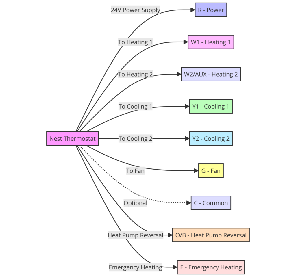
What’s Included in the Nest Thermostat Wiring Diagram?
The Nest wiring diagram typically includes the following components:
- Power Connections: This section shows the wires that provide power to the Nest thermostat, such as the C (common) wire, which is essential for the thermostat to function.
- HVAC System Connections: Here, you’ll find the wires that connect the Nest thermostat to your heating, ventilation, and air conditioning (HVAC) system, including the R (red), W (white), Y (yellow), and G (green) wires.
- Optional Connections: The diagram may also include optional connections, such as the O/B (orange/blue) wire for heat pumps or the ACC (accessory) wire for controlling additional HVAC equipment.
- Terminal Labeling: The diagram clearly labels the terminal connections on the Nest thermostat, making it easier to match the wires to the correct terminals.
Nest Thermostat Wiring Diagrams
Diagram 1:

Diagram 2:

Diagram 3:

How to Read the Nest Thermostat Wiring Diagram
Reading the Nest wiring diagram is straightforward. Start by identifying the connections on your current thermostat and match them to the corresponding terminals on the Nest diagram. Pay close attention to the wire colors and terminal labels to ensure a proper connection.
If you’re unsure about the wiring in your home, it’s always a good idea to take a picture of your existing thermostat wiring before disconnecting it. This will serve as a reference point and help you correctly match the wires to the Nest diagram.
Connecting the Nest Thermostat
Once you’ve identified the wires and understand the Nest wiring diagram, the next step is to connect the Nest thermostat to your HVAC system. The process typically involves the following steps:
- Turn off power to your HVAC system at the circuit breaker.
- Remove the existing thermostat and carefully label the wires to match the Nest diagram.
- Connect the labeled wires to the corresponding terminals on the Nest thermostat.
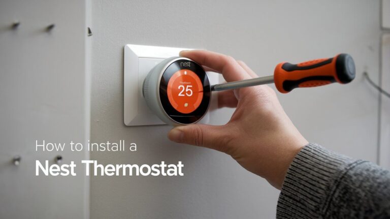
- Secure the Nest thermostat to the wall and power it on.
- Follow the on-screen instructions to complete the setup and configuration.
Remember to consult the Nest installation guide and the wiring diagram for detailed, step-by-step instructions specific to your HVAC system.
Additional Considerations
When working with the Nest wiring diagram, it’s essential to keep the following in mind:
- Compatibility: Ensure that your HVAC system is compatible with the Nest thermostat before attempting the installation.
- Wire Colors: While the Nest diagram uses standard wire color conventions, your existing wiring may not follow the same color coding. Focus on the terminal labels rather than the wire colors.
- Professional Assistance: If you’re unsure about the wiring or have any concerns, it’s always best to consult a professional HVAC technician for assistance.
By understanding and properly following the Nest thermostat wiring diagram, you can enjoy the benefits of this smart home device and take control of your home’s temperature and energy efficiency.


