Pioneer Wiring Diagram
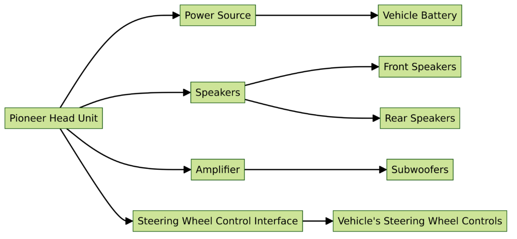
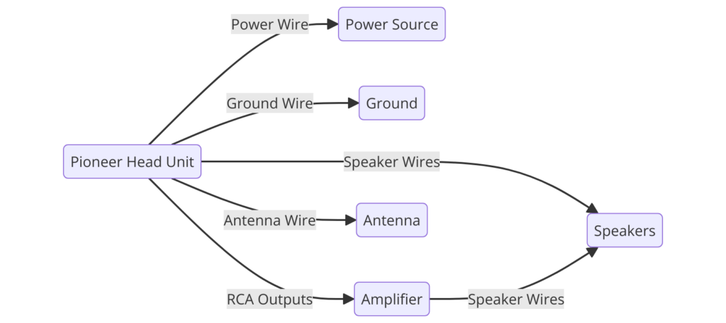
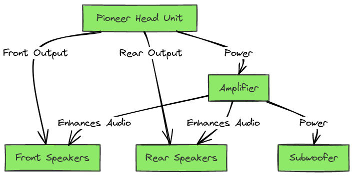
So what exactly is a Pioneer wiring diagram? Simply put, a Pioneer wiring diagram is a specialized schematic that maps out the interconnections between the components in your car audio system, as well as showing power and ground routing.
Whether you have a Pioneer head unit paired with an amplifier and speaker system or a more elaborate audio setup, the diagram will show how everything plugs in together – quite literally the wiring diagram maps out which wires and connectors make your audio system function. Besides showing how components physically connect, diagrams also spell out critical details on wire colors, label functions and electrical pathways.
Essentially, Pioneer wiring diagrams provide critical reference guides for audio hardware installation, upgrading and troubleshooting. They arm installers and do-it-yourselfers with granular understanding of Pioneer system wiring down to the color coding of individual wires. So next time you pop the hood to tweak your car’s audio hardware, be sure to keep your vehicle’s Pioneer wiring diagram on hand!
pioneer wiring diagrams
Diagram 1:

Diagram 2:

Diagram 3:

Diagram 4:

Diagram 5:

What’s Included in a Pioneer Wiring Diagram
Pioneer wiring diagrams include visual representations of the connections between:
- The head unit (the main stereo unit)
- Speakers
- Amplifiers
- Source units like CD players
- Any other wired accessories
The diagrams show:
- Wire colors
- Connector types and shapes
- What each wire or connector does
- An overview of how components connect
Standardized symbols are used for the different components, making Pioneer diagrams easy to follow even for beginners.
How to Read Pioneer Wiring Diagrams
With a wiring diagram in hand, hooking up your equipment is straightforward. Here’s how to interpret the diagrams:
1. Identify Wiring Colors
- The diagram will use standard colors like red, black, blue, white and gray to identify wires
- Power wires are typically red and ground wires black
- Colors are consistent across Pioneer models
2. Recognize Connector Types
- Wires connect to components via various connectors shown in the diagrams
- Common connectors are RCA jacks, speaker wire connectors, and power plugs
3. Spot the Labels
- Diagrams contain labels for the wire colors and connectors
- These labels spell out exactly what a wire is used for
- For example, labels might read “Front Left +” or “Subwoofer -”
4. Follow the Route
- Pathways show the routes wires take between components
- Arrows indicate signal or power flow direction
- Mapping the pathways helps visualize real-world wiring routing
With some focused examination of the color coding, connectors, labels and pathways, you’ll learn to navigate Pioneer wiring diagrams with ease.
Final Thoughts
In the beginning, peeking under the hood of your stereo system can feel akin to deciphering alien hieroglyphs. But wiring diagrams serve as invaluable reference guides for installations and repairs. With some diligent study of the color coding conventions, symbols and labels, you’ll be able to harness diagrams to help customize your car audio experience.
So don’t let wiring stand in the way of that sweet sound system upgrade you’ve been dreaming about. Arm yourself with a wiring diagram for your Pioneer stereo, turn some wrenches and unlock superior in-car acoustics. Let the smooth sounds roll!
