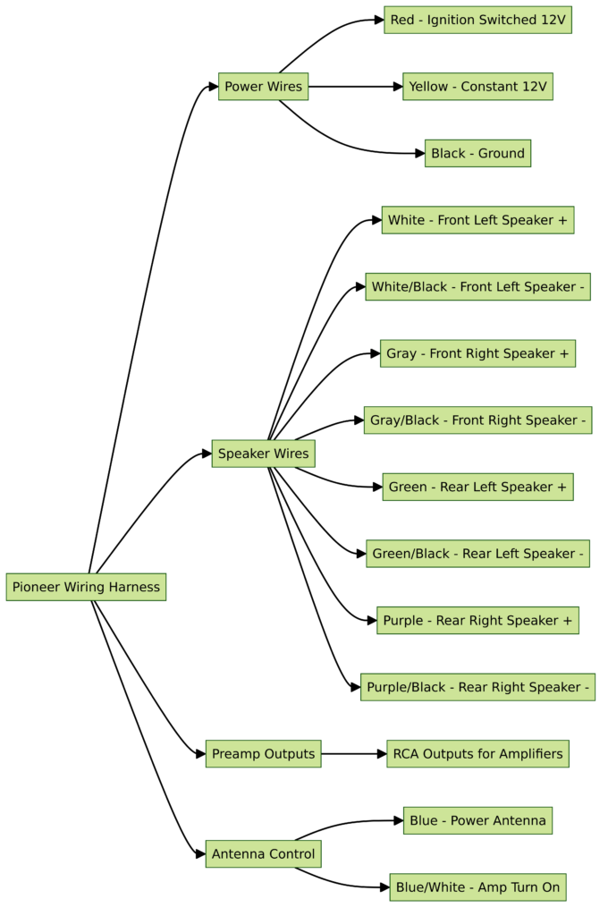
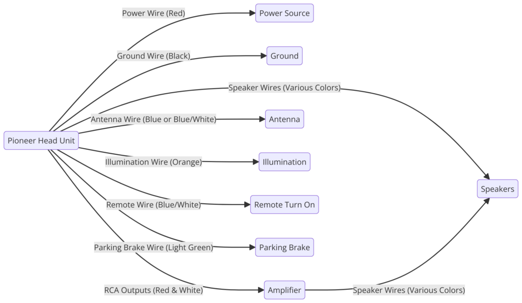
Pioneer Wiring Harness Diagram
Have you ever opened up your car stereo or navigation system and been greeted by a mess of wires with no idea what any of them do? Those tangled wires likely connect to something called a wiring harness, which links your device to power and other vehicle systems. Interpreting wiring harness diagrams is key to properly installing aftermarket car electronics like those made by Pioneer. This guide will provide tips on how to read Pioneer wiring schematics to connect your devices correctly.
Pioneer Wiring Harness Diagrams
Diagram 1:

Diagram 2:

Diagram 3:

Diagram 4:

Diagram 5:

What is a Wiring Harness?
A wiring harness is a set of wires bundled together to efficiently distribute power and signals. Harnesses have connectors at ends that plug into car stereo components and vehicle-specific adapter pieces. They simplify aftermarket installations by consolidating all necessary vehicle connections into an organized pre-made harness.
Parts of a Pioneer Wiring Harness
Pioneer wiring harnesses include the following parts:
- Power wires – Supply 12V DC power from battery
- Speaker wires – Connect speakers to receiver outputs
- Turn-on lead – Sends signal to turn device on/off
- Ground wire – Provides path to chassis ground
- Accessory wires – Optional 12V feed from ignition or dimmer
How to Read Pioneer Wiring Diagrams
Pioneer provides wiring diagram schematics with new car stereos and navigation systems to show installers how to properly connect them. Here is how to interpret these diagrams:
Diagram Symbols
- Thick lines – Power wires
- Thin lines – Signal wires
- Dotted lines – Option connections
- Brackets [ ] – Wire bundles
Wire Colors
- Red – 12V constant power (memory)
- Yellow – 12V switched power
- Black – Ground
- Blue/white – Remote turn-on signal
- Green/Black – Speaker wires
So if you see a [Red, Yellow, Black] bundle, you know those connect the constant and switched 12V power.
Connector Pinouts
Pinouts on connectors indicate wire positions. Common Pioneer harness plugs have connections as follows:
- A) Rear left + speaker
- B) Rear left – speaker
- C) Front left + speaker
- D) Front left – speaker
- Constant 12V
- Switched 12V
- Remote turn-on
So pin A1 connects to the rear left positive speaker wire, while pin D2 goes to the front left negative speaker.
How to Connect a Pioneer Wiring Harness
Once you understand the diagram symbols, connecting a Pioneer harness is straightforward:
- Match harness plugs to car stereo
- Connect harness power wires to matching colors from battery wires
- Ground black wire to metal chassis or bolt
- Connect accessory and signal wires to vehicle wires with same functions
- Plug speaker wires into rear channels of receiver
It also helps to use a vehicle-specific wiring adapter with the harness for easy installation. Test operation once everything is securely connected.
Final Thoughts
Reading wiring schematics is an essential skill for installing aftermarket electronics. Fortunately, Pioneer diagrams clearly convey how harnesses should be connected once you learn the basic symbols and color coding. With harness and vehicle wire connections matched, you can enjoy superior sound from your new Pioneer stereo or navigation system.
