Demystifying Radio Wiring Diagrams for Stress-Free Installations
Whether you just got a new car stereo as a gift or finally decided to upgrade your old radio, installing your new head unit with the proper car audio wiring can be confusing. One wrong connection of a wire and you could damage your entire car’s electrical system. Where do you start to make sense of the spider web of wires behind your dashboard?
That’s where radio wiring diagrams come in. These schematics, usually found online or included with any new stereos, are the _key to seamlessly integrating your head unit into the existing connections in your car. If those terms went over your head, don’t worry. This guide will provide a foolproof walkthrough of radio wiring with diagrams to ensure safe and seamless functionality.
We’ll demystify exactly what a wiring diagram is, why it’s so valuable, and how to use it. You’ll learn how to:
- Read car stereo wiring color codes
- Connect an aftermarket car stereo properly
- Troubleshoot any issues
- Safely install a radio by yourself!
Let’s start by answering a fundamental question.
What is a Radio Wiring Diagram?
In simple terms, a radio wiring diagram is a schematic that outlines what each wire in your car’s stereo wiring harness does, and where it needs to be connected. Think of it like a roadmap for properly integrating your new or existing car radio into your vehicle’s electrical system.
Most factory car stereos and aftermarket car stereos come with this schematic to make installations easier for DIYers. You’ll usually find a radio wiring diagram printed on a small card included in your owner’s manual packet. If not, a quick web search for your specific car model should turn it up.
Modern car stereo wiring diagrams have evolved to use uniform wire color codes and connector labeling. That wasn’t always the case, and older car audio components can vary. However, most follow basic conventions as outlined below.
Now you know what a wiring diagram is and why having the right one for your specific radio and car model is so essential. Next let’s cover how you actually decipher and use one.
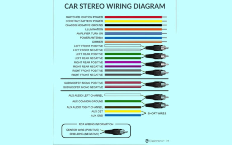
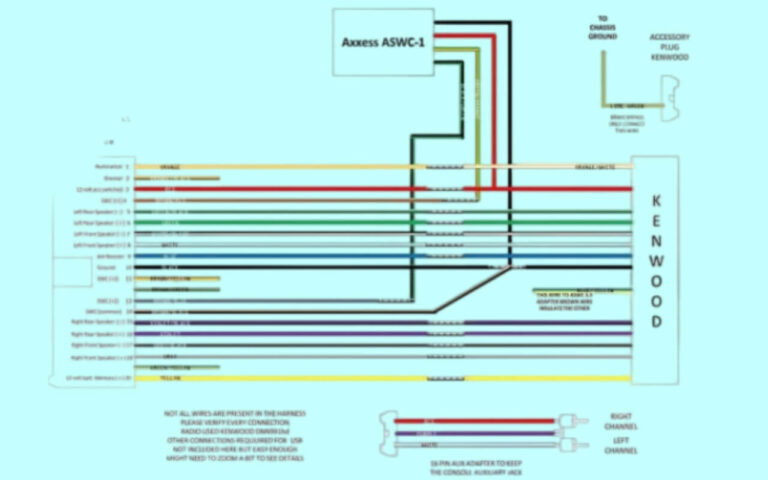
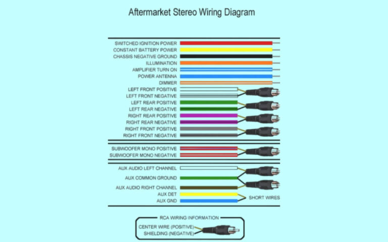
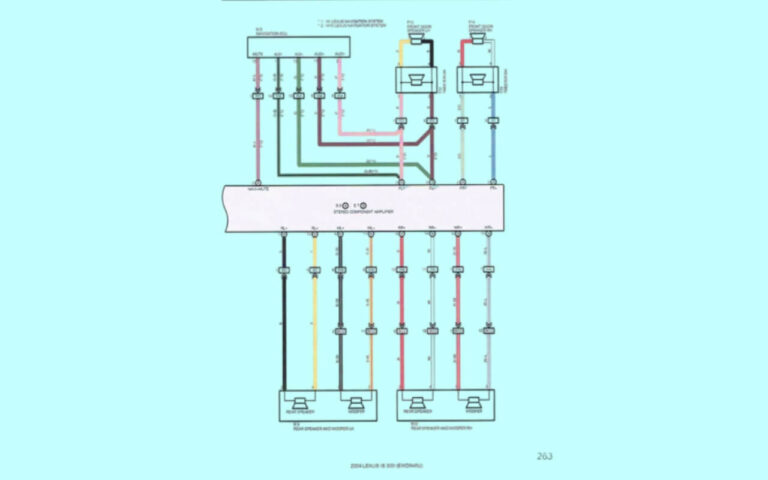
Radio Wiring Diagrams
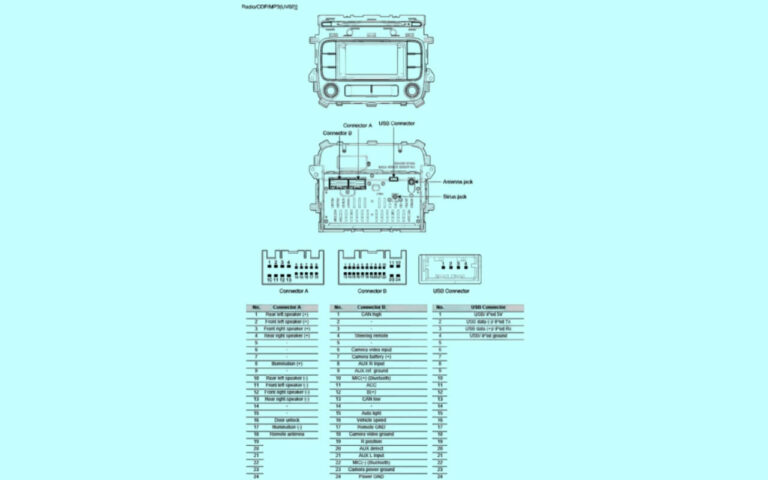
Diagram 1:

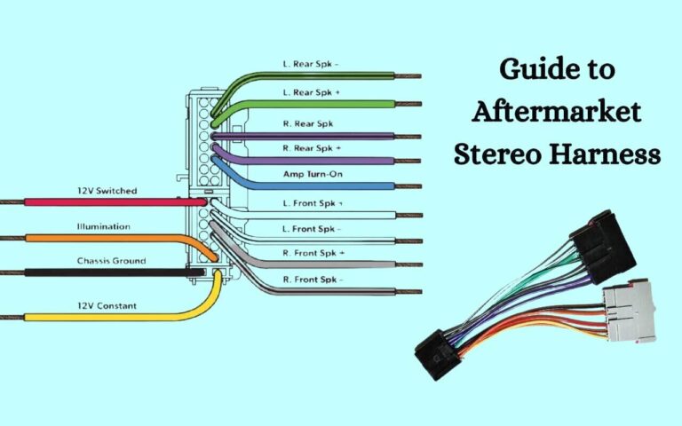
Diagram 2:
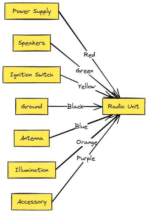
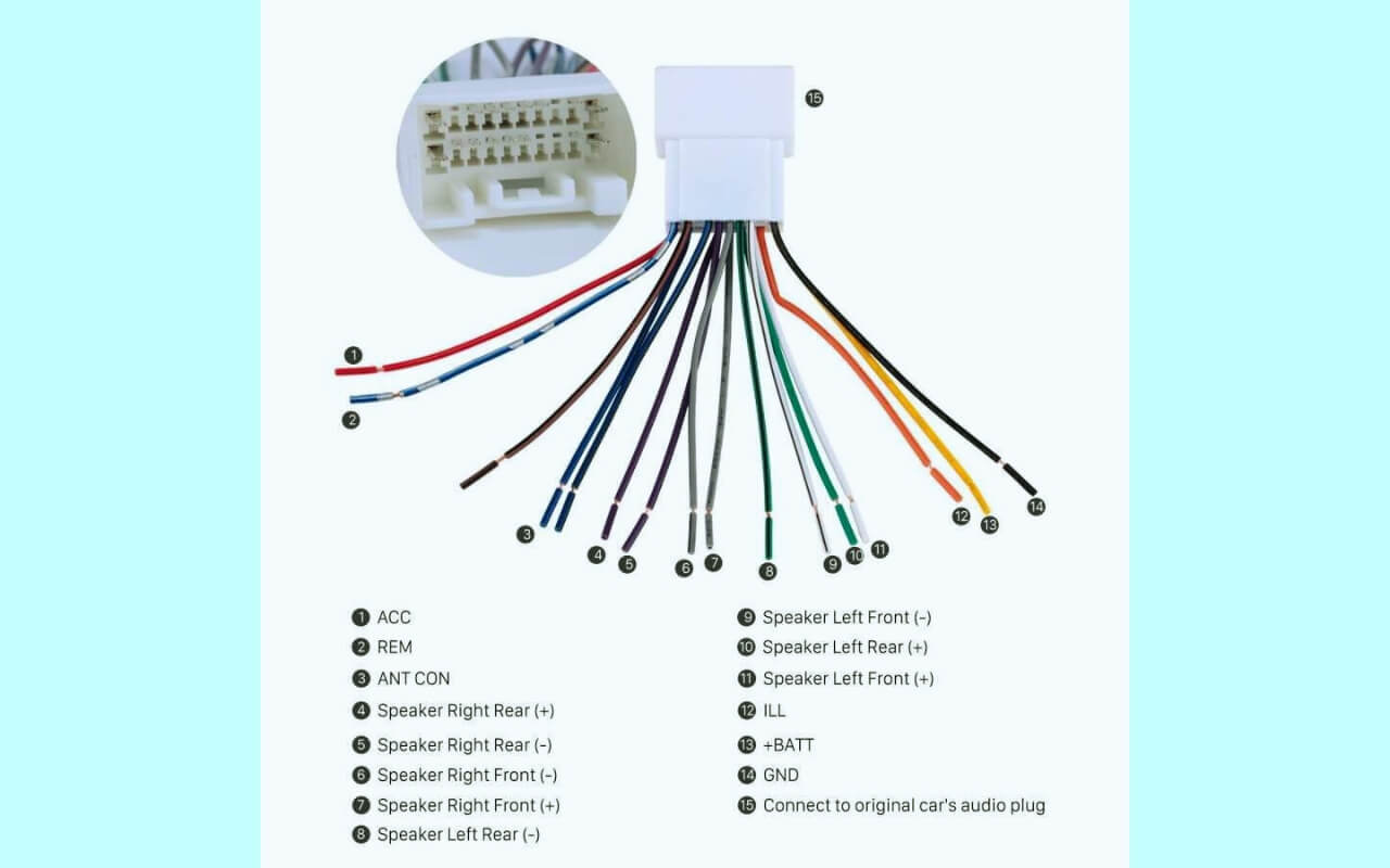
Diagram 3:

Diagram 4:

How to Read Car Stereo Wiring Diagrams
Many first-time car audio installers find radio wiring diagrams intimidating at first glance. All those different colored wires twisting around each other can feel overwhelming! However, these schematics are actually simple to use once you know the key components to look for.
Most radio wiring diagrams have three main elements:
- Wiring harness connector
- Wire splices
- Component connectors
Let’s break down what each section tells you.
Wiring Harness Connector
This is the plug that connects your new or existing stereo directly into your car’s electrical system.
- Locate the wiring harness in your car that will link your head unit to the speakers, display, controls, amplifier, and antenna.
- Use the diagram splice info to connect matching colored wires from harness to their corresponding stereo component.
Wire Splices
These indicate all connection points along the length of each colored wire from your stereo harness:
- Follow where each wire routes based on the spec diagram
- Use splice info to tap accessory wires like amp turn-on, power antenna, etc along their path.
- Avoid splicing unrelated circuits together.
Component Connectors
Connectors show the other endpoints for each harness wire, like speakers, controls and external amps:
- Use shapes and/or labels to locate mating terminals.
- Splice into the right point along a wire run to attach components.
- Polarity indicators (+/-) crucial for speakers.
Armed with the basics of how to trace a radio wiring diagram, let’s cover some key tips for using them safely and effectively.
Essential Tips for Using Wiring Diagrams
When tackling your first car stereo wiring project, these pro tips will make the installation process smoother:
- Confirm you have the right schematic – Double check any diagram using your car make, model and year. Also verify it matches your head unit.
- Check connectors before splicing – Ensure the harness clip connects correctly before tapping any wires.
- Route wires cleanly – Avoid kinks and safely tuck cables along their factory paths. Use grommets when running through metal.
- Label connections – Color code or tag splices to other components for easier diagnosis later.
- Take precautions before turning power on – Confirm no bare wire exposure and fuses are sound.
- Test stereo before reassembly – Power up your new radio and verify sound prior to securing everything. This allows easier troubleshooting rather than taking trim panels on and off repeatedly.
Those core installation best practices will ensure your wiring work goes smoothly. Next let’s decode the meaning behind common car stereo wire color codes.
Radio Wire Color Codes Deciphered
The key to tapping into your car’s wire radio wiring correctly is understanding what each colored wire indicates. While some variance exists between car manufacturers, most follow a fairly standard convention:
- Yellow: Constant 12V Power – Connects head unit to battery and ignition. Always live.
- Red: Accessory Switched Power – Powered when ignition is turned on only.
- Black: Vehicle Ground – Required for completing all circuits back to negative battery terminal.
- Blue: Power Antenna Turn-On – Provides power for motorized antenna when radio is on.
- White: Left Front Speaker (+) – Extends to left front car speaker positive terminal when head unit speaker output is active.
- White/Black: Left Front Speaker (-) – Same but with negative polarity to left front speaker.
- Gray: Right Front Speaker (+) – Positive feed to right front speaker.
- Gray/Black: Right Front Speaker (-) – Right front speaker negative connection.
- Green: Left Rear Speaker (+) – Positive wire for left rear car speakers.
- Green/Black: Left Rear Speaker (-) – Left rear speaker negative wire splice point.
- Purple: Right Rear Speaker (+) – Right rear speaker positive.
- Purple/Black: Right Rear Speaker (-) – Right rear negative speaker terminals get connected.
Keep in mind, the specific colors can vary across car stereo brands and models. However, the component groupings are fairly standard.
Armed with knowledge of basic car radio wiring color codes, let’s shift gears to making sense of aftermarket car stereo wiring harness adapters.
Aftermarket Car Stereo Wiring Adapters Demystified
Upgrading your outdated factory car stereo often requires splicing a new radio’s wiring harness into your car’s existing connection points. Since not all vehicles have uniform plugs and outlets, harness “adapters” are commonly used.
These harness adapters have a standard car stereo side, and a connector that mates directly into specialized plugs used by car manufacturers like Honda, Toyota, Nissan and others. This allows an aftermarket stereo to integrate into the unique radio cavity and wiring configuration found across makes & models.
The adapter connectors also account for inconsistencies in wire color codes across vehicles, and translate that onto a standardized car stereo wire harness. This simplifies proper system connections drastically versus manually splicing each wire’s function.
Harness adapters can be obtained at any car audio specialty retailer. Many also allow connecting an auxiliary A/V input cable tailored for your smartphone or MP3 player. Just ensure it’s designed specifically for your vehicle before purchase. Now let’s explore some keyed wire harness connector basics common across stereos.
Understanding Radio Wiring Harness Connectors
As you dive into your new car audio project, you’ll likely need to disconnect your factory wiring harness to attach your new aftermarket stereo’s harness. Pay attention to how the connector is keyed or aligned to avoid reversing important power, ground and speaker channels.
Note terminals designated with positive or negative symbols indicating speaker polarities. Mixing these up can inhibit sound quality or even blow out a speaker!
You’ll also want to locate connectors designated for linking up amplified subwoofers or adding auxiliary audio sources like smartphones down the line. Identifying these now will make expanding your system later much simpler.
Next we’ll cover some best practices for decoding factory car stereo wiring schematics. This is the trickiest type you may encounter since automakers utilize proprietary connectors and conventions.
Making Sense of Factory Car Stereo Wiring Diagrams
The most challenging car audio wiring scenario is when trying to add an aftermarket stereo in a vehicle with a factory amp. Integrating into the automaker’s complex audio circuitry ratchets complexity up significantly.
Fortunately most vehicle manufacturers provide radio wiring diagrams, either printed or accessible online through their support sites. You’ll need three key details that should be indicated:
- Connector pinout – what each cavity in the factory harness plug is used for.
- Wire color/function – decoding OEM colors since they often differ from aftermarket standards.
- Warning and cautions – specifies oddities or risks specific your car model.
Additionally, some higher end amplifiers require integration harnesses that convert proprietary controls to align with aftermarket units. The diagram should indicate whether this is compulsory. Make sure you have the appropriate harness adapter before tackling the project.
Ok, at this point we’ve covered a ton of wiring diagram specifics as well as harness connectors and color codes. Next let’s consolidate some of the most common questions DIYers have about deciphering car stereo wire schematics.
Top 10 Questions about Car Audio Wiring Diagrams
Let’s review answers to some of the most frequently asked questions about using wiring diagrams for car stereo installations:
1. Do aftermarket car stereos come with wiring diagrams?
Yes, the vast majority include either a printed wiring schematic or instructions indicating where to access the diagram online for that specific model.
2. What is the best source for radio wiring diagrams?
Always check the installation manual for your car or new stereo first. If unavailable there, the12volt.com has an expansive database of automotive wiring diagrams submitted by users across most makes and models.
3. What if my car stereo wiring diagram is unavailable?
In the worst case without a readily available car radio wiring diagram, use a multimeter to trace wiring color functions prior to tapping any wires.
4. Do car stereo wiring adapters eliminate the need for wiring diagrams?
Largely yes, since they convert any automaker custom wiring into a standardized harness. But having the right schematic is still recommended to identify auxiliary ports and accessory power taps.
5. Can connecting wires incorrectly permanent damage car electrical systems?
Absolutely! Reversing speaker polarities or power/ground circuits can potentially damage amplifiers, your vehicle ECU or other electronics. Always double checkwiring even when using adapters.
6. How are car stereo installers able to connect everything without diagrams?
Professionals have access to extensive databases of factory and aftermarket wiring details. But whenever possible, they still utilize available schematics to confirm terminal functions and avoid assumptions.
7. If my wiring checks out, what else can cause problems?
Assuming wiring is sound, the most common car stereo issues otherwise come down to incorrect settings, faulty components or bad audio source material.
8. Can I splice into wires without modifying factory connectors?
Often yes. Some amount of free wire is usually available allowing you to splice into the insulation without actually disturbing the connectors. This avoids compromising their integrity.
9. Is a wiring harness tester worth getting?
A wire harness tester that injects signals is invaluable for not only verifying connections, but also tracing unmarked OEM wires without need for a schematic. Their usefulness justifies the $50 or so dollar investment.
10. Why do car stereos use so many different colored wires?
In short – flexibility. Multi-conductor cabling allows systems to expand by adding wires for features like auto EQs and navigation overlays. The colors distinguish their distinct functions at a glance.
Alright, armed with plenty of car audio wiring details, let’s shift into practical territory and walk through installing an aftermarket stereo from start to finish.
DIY Installation of an Aftermarket Car Stereo
We’ll now step through the full process for swapping your old factory radio out for a modern Bluetooth-enabled aftermarket stereo. The exact dashboard disassembly steps can vary, but once access is gained the wiring process is very similar across all vehicle makes and models.
Stereo Removal
First let’s remove your existing radio components safely:
- Make sure ignition is off and key is removed before unplugging anything
- Unscrew any securing brackets connecting stereo to dash kit
- Unseat connectors by squeezing release tabs before yanking wires
- Temporarily place radio out of your way while leaving all wires connected
New Stereo Wiring Prep
Now let’s prep your new head unit prior to installation:
- Obtain necessary dash installation kit and wiring harness adapter for your car
- With stereo outside car, connect harness adapter via color coded wires
- Tuck loose harness end down side of new stereo to keep together
- Preset any settings on your new radio using front controls
Vehicle Wiring
Under the dash, locate factory wiring and head unit connectors:
- Unplug all existing connectors linking to previous stereo
- Attach vehicle wiring harness adapter to factory harness/plugs
- Route loose pigtail to new stereo location and connect head unit
Install and Test
Almost ready to jam out! Let’s finalize integration:
- Secure new stereo to dash kit using provided hardware
- Reconnect trim panels and snap back into place
- Review wiring a final time before starting vehicle
- Turn key forward and verify new stereo powers on
- Test speakers and controls to ensure proper operation
- You now have tunes!
With your new head unit fully functioning, let’s cover some troubleshooting tips in case any issues emerge down the road.
Diagnosing Car Stereo Wiring Problems
In an ideal world the wiring process would be plug-and-play, and you’d be the envy of all your friends with your flashy new touchscreen stereo! Unfortunately though, gremlins in the form of shorts or faulty connections can arise down the road and disable your system.
Here are some common wiring-related issues along with the likely causes:
- Display works but no sound – Speaker wires may have corroded or detached. Verify connections securing all four speaker channel attachments (+ and -) at both the stereo and speaker ends.
- Speakers emit crackling or distorted output – If just one side (left or right) has issues, balance control fade can help isolate whether wires or that speaker itself are faulty. Also ensure bare speaker wiring isn’t grounding to chassis.
- Stereo keeps blowing internal fuse – Constant short circuit due to pinch exposed power wire or reversed polarity connection (red to ground). Thoroughly inspect wires removing any stray strands contacting car body.
- Head unit doesn’t retain presets/settings with ignition off – Likely the red ACC wire doesn’t have constant +12V when car is powered down. Try switching to the yellow +12V line.
- Alternator whine that varies with RPM – Ensure the black grounding wire has a solid chassis contact. Isolate and tie down any loose wire segments causing interference.
- Display is dim or cutting out – If not wiring related, can be due to weak stereo backlight brightness control circuit not syncing properly with dashboard light voltage.
Having covered common wiring trouble scenarios, let’s finish up with some key installation best practices that can help avoid any electrical gremlins in the first place.
Expert Tips for Clean Routing of Wires
Taking time to cleanly route all your car stereo wiring during initial installation will pay dividends down the road in reliability and ease of future enhancements or troubleshooting needs.
Here are some professional wire routing tricks:
- Utilize plastic grommets whenever running wires through metal frames to avoid shorts
- Adhere wire bundles alongside factory looms using factory clip anchors
- Wrap bungee ties evenly spaced to avoid sagging and prevent rattling
- Route longest wire spans first, leaving room for shorter runs to avoid bunching
- Use spiral loom wrap to consolidate related bundles along common paths
- Lubricate threads of screw terminals to avoid overtightening during reinstalls
It’s tempting to just stuff all the wiring behind panels and call it done. Resist that urge! A clean wiring job is just as crucial as proper electrical connectivity for the longevity of your car audio investment.
Safety Best Practices When Working with Car Audio Wiring
Anytime you take trim pieces apart and access electrical systems in your vehicle, it’s wise to take some basic precautions. Here are a few to keep in mind:
- Remove jewelry and watches – avoids electrical shorts and scratched surfaces
- Disconnect battery – safest option is to disconnect negative terminal when splicing wires
- Use eye protection – prevents injury from debris when pulling panels temporarily
- Avoid socks/shoes with holes – reduces risk of losing small hardware in carpeting void
- Watch for airbag warnings – don’t disable SRS components or sensors to access stereo
- Keep small parts organized – take photos before dismantling complex trim pieces
Also ensure you only perform stereo work on level, well-lit surfaces in areas clear of vehicle traffic. Taking sensible safety measures will assure you don’t end up hurting yourself or damaging your car’s delicate electronic systems. Rushing through an installation heightens the likelihood of wiring mishaps or component failures down the road.
Conclusion
Understanding car stereo wiring diagrams not only assures painless installations, but also empowers you to enhance and troubleshoot audio components down the road. We’ve demystified schematic specifics ranging from wire color coding conventions to harness connector configurations across factory and aftermarket systems. Armed with basics covered here, you can now fearlessly integrate amps, smartphones and other add-ons as your audio needs evolve.

