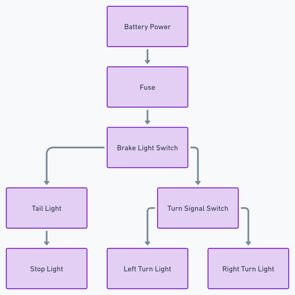
Stop/Turn/Tail Light Wiring Diagram
A stop/turn/tail light wiring diagram is a crucial resource for understanding the electrical system responsible for the essential lighting components on the rear of a vehicle. This diagram provides a visual representation of how the various wires, connectors, and electrical components work together to ensure the proper functioning of the brake lights, turn signals, and taillights. Whether you’re a do-it-yourself mechanic, an auto enthusiast, or simply someone who wants to better understand the workings of their vehicle, understanding this diagram can be immensely helpful.
What’s Included in a Stop/Turn/Tail Light Wiring Diagram?
A typical stop/turn/tail light wiring diagram will include the following components:
- Brake light circuit: This circuit is responsible for activating the brake lights when the brake pedal is pressed.
- Turn signal circuit: This circuit controls the blinking of the turn signal lights, indicating the driver’s intention to turn or change lanes.
- Taillight circuit: This circuit powers the taillights, which illuminate the rear of the vehicle for visibility and safety.
- Wiring connections: The diagram will show how the various wires are connected between the light components, the vehicle’s electrical system, and the control switches.
- Fuses and relays: The diagram may also include information about the fuses and relays that protect the electrical circuits and ensure the proper operation of the lighting system.
Stop/Turn/Tail Light Wiring Diagrams
Diagram 1:

Diagram 2:

Diagram 3:

How to Read a Stop/Turn/Tail Light Wiring Diagram
Reading a stop/turn/tail light wiring diagram may seem daunting at first, but with a bit of practice, it becomes a valuable tool for understanding and troubleshooting your vehicle’s electrical system. Here are some tips to help you navigate the diagram:
- Identify the main components: Locate the brake lights, turn signals, and taillights on the diagram, and trace the wiring connections back to the vehicle’s electrical system.
- Follow the color-coded wires: Wiring diagrams often use color-coding to differentiate between the various circuits. Pay attention to the wire colors to understand how the different components are connected.
- Understand the symbols: The diagram may use standard electrical symbols to represent components like switches, relays, and connectors. Familiarize yourself with these symbols to interpret the diagram more effectively.
- Trace the circuits: Start with a specific component, such as the brake lights, and follow the wiring connections to understand how the circuit is designed and how it interacts with the other lighting components.
Troubleshooting and Maintenance
Understanding the stop/turn/tail light wiring diagram can be invaluable when it comes to troubleshooting and maintaining your vehicle’s lighting system. If you encounter an issue, such as a malfunctioning brake light or turn signal, you can refer to the diagram to identify the potential problem areas and make the necessary repairs or replacements.
Additionally, the wiring diagram can be useful when installing aftermarket lighting components or upgrading your vehicle’s lighting system. By understanding how the existing system is wired, you can ensure that any modifications or additions are done in a safe and effective manner, without compromising the overall electrical integrity of your vehicle.
Conclusion
The stop/turn/tail light wiring diagram is an essential resource for anyone who wants to understand the workings of their vehicle’s lighting system. By familiarizing yourself with this diagram, you can gain a better appreciation for the complexity of the electrical systems in modern vehicles and be better equipped to troubleshoot and maintain your car’s lighting components. Whether you’re a seasoned mechanic or a curious car owner, mastering the stop/turn/tail light wiring diagram can be a valuable skill that can save you time, money, and headaches down the road.
