Thermostat Wiring Diagram
Thermostats play a crucial role in regulating the temperature in our homes and offices, ensuring a comfortable living or working environment. However, understanding the intricate wiring of a thermostat can be a daunting task, especially for those unfamiliar with electrical systems. Fear not, as this comprehensive guide will demystify the thermostat wiring diagram, empowering you with the knowledge to tackle this task with confidence.
A Sneak Peek into the Thermostat Wiring Diagram
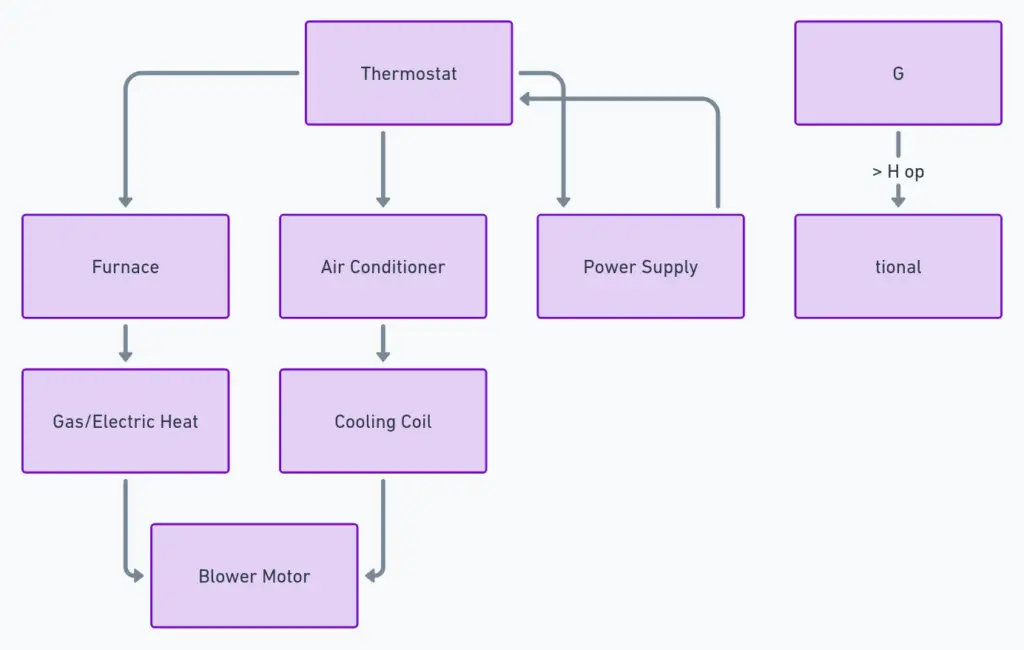
A thermostat wiring diagram is a visual representation that illustrates the connections between the thermostat and the heating, ventilation, and air conditioning (HVAC) system. It serves as a roadmap, helping you navigate the intricate web of wires and terminals, ensuring proper installation and functionality.
Thermostat Wiring Diagrams
Diagram 1:

Diagram 2:

Diagram 3:

What’s Included in a Thermostat Wiring Diagram?
A typical thermostat wiring diagram encompasses the following components:
- Thermostat: The control center that regulates the temperature by sending signals to the HVAC system.
- HVAC System: This includes the furnace, air conditioner, or heat pump responsible for heating or cooling the space.
- Wires: Color-coded wires that carry signals and power between the thermostat and the HVAC system.
- Terminals: Labeled connection points on the thermostat and HVAC system where the wires are attached.
Decoding the Thermostat Wiring Diagram
Reading a thermostat wiring diagram may seem like deciphering a secret code, but fear not! Follow these simple steps, and you’ll be a pro in no time:
- Identify the Components: Locate the thermostat, HVAC system, and any other relevant components on the diagram.
- Wire Colors: Take note of the color-coding system used for the wires, as each color represents a specific function or connection.
- Terminal Labels: Match the wire colors to the corresponding terminal labels on the thermostat and HVAC system.
- Follow the Connections: Trace the path of each wire from the thermostat to the HVAC system, ensuring that the connections are correct.
Understanding Wire Functions
To fully grasp the thermostat wiring diagram, it’s essential to understand the purpose of each wire:
- R (Red): This wire carries the power supply from the HVAC system to the thermostat.
- W (White): Responsible for activating the heating system.
- Y (Yellow): Controls the cooling system or air conditioner.
- G (Green): Operates the fan or blower motor.
- C (Common): Provides a neutral or ground connection for the thermostat.
Additional Headings and Topics
- Common Wiring Configurations: Explore the different wiring setups for various HVAC systems, such as heat pumps, furnaces, and air conditioners.
- Troubleshooting Tips: Discover how to identify and resolve common wiring issues that may arise during installation or maintenance.
- Safety Considerations: Learn about essential safety precautions to take when working with electrical components and wiring.
- Smart Thermostat Integration: Understand how to integrate smart thermostats with your existing HVAC system and wiring.
Putting It All Together
Mastering the thermostat wiring diagram is a crucial step in ensuring the efficient operation of your HVAC system. By following the guidelines outlined in this comprehensive guide, you’ll be equipped with the knowledge to tackle this task confidently. Remember, proper wiring not only ensures comfort but also contributes to energy efficiency and cost savings.
Whether you’re a DIY enthusiast or a professional HVAC technician, understanding the thermostat wiring diagram is an invaluable skill. Embrace the challenge, and let this guide be your trusted companion on your journey to temperature control mastery.


